
Air conditioner for vehicle

a technology for air conditioners and vehicles, applied in vehicle heating/cooling devices, vehicle components, transportation and packaging, etc., can solve problems such as increased repair costs of exterior heat exchangers, leakage into vehicle interiors, and damage to exterior heat exchangers

Active Publication Date: 2017-02-02
DENSO CORP
View PDF16 Cites 34 Cited by
  • Summary
  • Abstract
  • Description
  • Claims
  • Application Information

AI Technical Summary

Benefits of technology

The patent text describes a solution to prevent damage to the exterior heat exchanger of a vehicle in the event of a collision, which could increase repair costs or lead to environmental destruction. The solution involves replacing the exterior heat exchanger with a heat exchanger that circulates coolant, which prevents the refrigerant from leaking into the vehicle interior and minimizes repair costs and environmental damage.

Problems solved by technology

Accordingly, when the refrigerant leaks to the evaporator or the condenser, it may also leak into the vehicle interior.
In addition, since an exterior heat exchanger which performs one of the condensation and evaporation of a refrigerant is conventionally disposed in the forefront of a vehicle, the exterior heat exchanger may be destroyed even in the event of slight collision in which the critical components (frames, drive mechanisms, motors, etc.) of a vehicle body are not damaged.
For this reason, the repair cost of the exterior heat exchanger may be increased due to the refilling of the refrigerant, or the refrigerant having a high warming potential may be discharged to the atmosphere.

Method used


Image

  • Air conditioner for vehicle
  • Air conditioner for vehicle
  • Air conditioner for vehicle

Examples


first embodiment

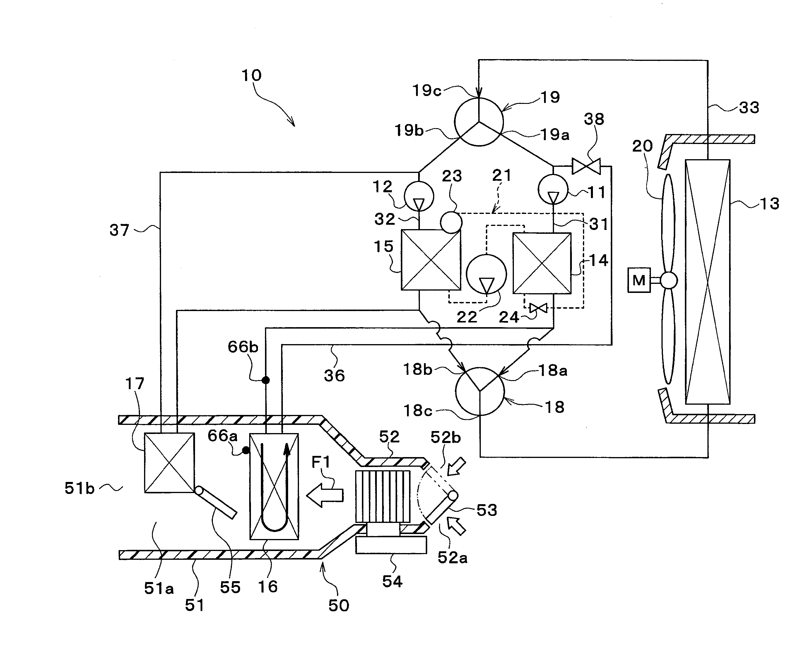
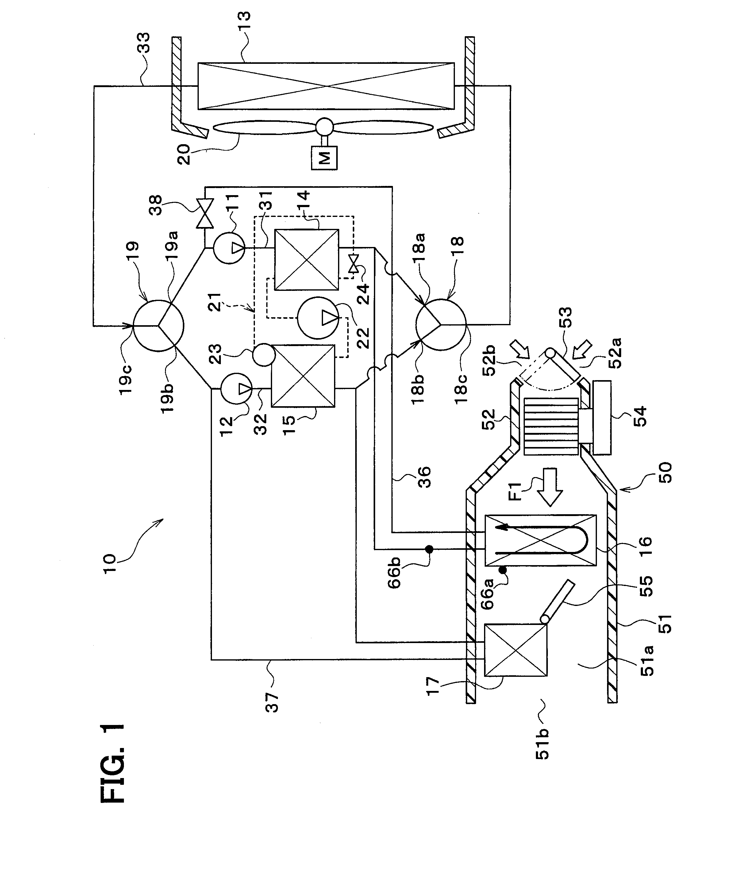
[0059]A vehicle thermal management system 10 illustrated in FIG. 1 is used to properly regulate the temperatures of a variety of devices included in a vehicle and a vehicle interior. In the embodiment, the thermal management system 10 is applied to a hybrid vehicle which obtains driving force for vehicle traveling from an engine (internal combustion engine) and a traveling electric motor.

[0060]The hybrid vehicle of the embodiment is a plug-in hybrid vehicle in which electric power supplied from an external power source (commercial power source) may be charged to a battery mounted in the vehicle (in-vehicle battery) when the vehicle is stopped. A lithium-ion battery may be used as an example of the battery.

[0061]The driving force output from the engine is used to drive the vehicle and to operate a generator. The electric power generated by the generator and the electric power supplied from the external power source may be stored in the battery. The electric power stored in the batter...

second embodiment

[0280]In the above first embodiment, the flow rate of coolant flowing in the cooler core 16 is controlled in the frost restriction mode. However, in the present embodiment, the coolant temperature flowing in the cooler core 16 is controlled in the frost restriction mode.

[0281]As illustrated in FIG. 17, an electric heater 70 is disposed in the cooler core passage 36. The electric heater 70 is a heating element which generates heat by electric power supplied. The coolant flowing in the cooler core passage 36 is heated by heat generated by the electric heater 70. The operation of the electric heater 70 is controlled by the controller 60.

[0282]In the embodiment, the configuration (hardware and software) for controlling the operation of the electric heater 70 in the controller 60 is referred to as an electric heater control unit 60h. The electric heater control unit 60h may be configured independently of the controller 60. The electric heater 70 and the electric heater control unit 60h a...

third embodiment

[0286]In the above second embodiment, the coolant temperature flowing in the cooler core 16 is increased by heating the coolant by the electric heater 70. However, in the present embodiment, the coolant temperature flowing in the cooler core 16 is increased by mixing coolant heated by the coolant / heater 15 with coolant cooled by the coolant / cooler 14, as illustrated in FIG. 18.

[0287]A first communication passage 71, a second communication passage 72, a first communication on-off valve 73, and a second communication on-off valve 74 are added to the embodiment.

[0288]The first communication passage 71 is a passage through which the coolant inlet-side portion of the cooler core 16 in the cooler core passage 36 communicates with the coolant inlet-side portion of the cooler core 16 in the heater core passage 37.

[0289]The second communication passage 72 is a passage through which the coolant outlet-side portion of the cooler core 16 in the cooler core passage 36 communicates with the coola...


PUM


Abstract

An air conditioner for a vehicle includes: a pump configured to take in and discharge a heat medium; a first heat medium / air heat exchanger disposed to regulate a temperature of ventilation air blown into a vehicle interior by conducting sensible-heat exchange between the ventilation air and the heat medium circulated by the pump; a first heat transfer device having a passage through which the heat medium flows and disposed to conduct heat transfer with the heat medium circulated by the pump; a heat medium temperature regulator disposed to regulate the temperature of the heat medium circulated by the pump; and a heat exchanger regulator disposed to regulate a heat transfer amount with the heat medium in the first heat transfer device or heat exchange capability of the first heat medium / air heat exchanger such that a temperature associated with a temperature of the ventilation air regulated by the first heat medium / air heat exchanger approaches a first target temperature.

Description

CROSS REFERENCE TO RELATED APPLICATION[0001]This application is based on Japanese Patent Application No. 2013-268580 filed on Dec. 26, 2013, the contents of which are incorporated herein by reference in its entirety.FIELD OF THE INVENTION[0002]The present disclosure relates to an air conditioner used for a vehicle.BACKGROUND ART[0003]Conventionally, Patent Document 1 discloses a vehicle air conditioner that cools ventilation air blown into a vehicle interior using an evaporator and heats the air using a condenser.[0004]The evaporator is a heat exchanger which exchanges heat between a low-pressure side refrigerant and ventilation air in a refrigeration cycle so as to evaporate the low-pressure side refrigerant and simultaneously cool the ventilation air. The condenser is a heat exchanger which exchanges heat between a high-pressure side refrigerant and ventilation air in the refrigeration cycle so as to condense the refrigerant and simultaneously heat the ventilation air.[0005]In the...

Claims


Application Information

Patent Timeline
IPC IPC(8): B60H1/00B60H1/24B60H1/08
CPCB60H1/00899B60H1/08B60H2001/00928B60H1/00278B60H1/24B60H2001/00307B60H1/32284
Inventor ENOMOTO, NORIHIKOKAKEHASHI, NOBUHARUKATOH, YOSHIKIKUWAYAMA, KAZUTOSHIMAKIHARA, MASAMICHI
Owner DENSO CORP
Learn More