
Method of Injection Molding USing One or More Strain Gauges as a Virtual Sensor

Active Publication Date: 2017-01-26
IMFLUX INC
View PDF10 Cites 6 Cited by
  • Summary
  • Abstract
  • Description
  • Claims
  • Application Information

AI Technical Summary

Benefits of technology

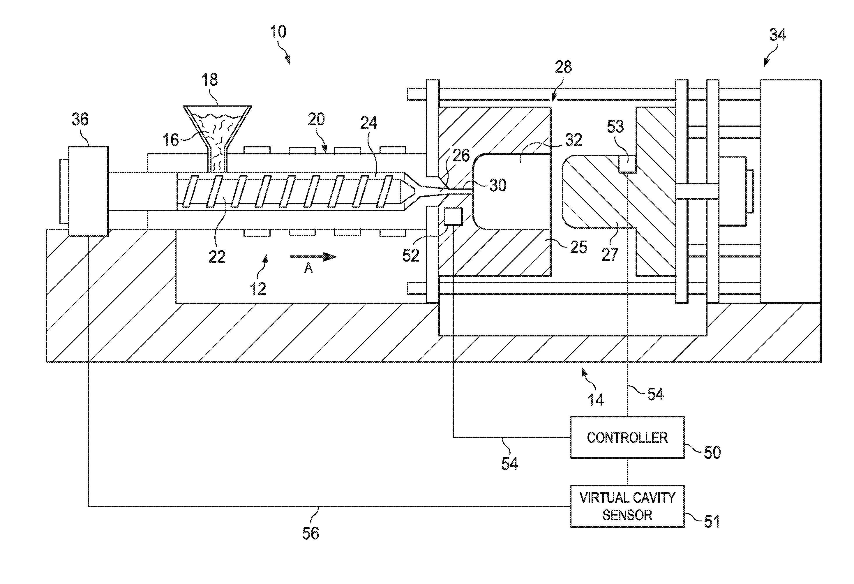
The present patent describes a pressure sensing system for an injection molding process. The system uses strain gauges to measure the pressure at the melt flow front, which is the area where the material is first heated and formed into the desired shape. If the measured pressure exceeds a certain level, the system can modify the operation of the molding machine to bring the pressure back to within a pre-set range. The system also includes a virtual cavity sensor, which is a software program that reads data from the strain gauges and compares it to an optimal pressure-time curve to determine how well the molding process is going. This virtual sensor can provide feedback to the molding machine to correct any deviations from the optimal pressure-time curve. Overall, the system helps to improve the production of injection molded parts by ensuring optimal pressure control during the process.

Problems solved by technology

The pressure within the mold cavity is an important vector, as insufficient pressure may result in improperly formed parts while excessive pressure may result in damage to the mold.
Direct sensors, such as sensors placed within a mold cavity, leave undesirable marks on part surfaces.
For example, while demand for injection molded parts with high gloss finishes has been increasing, direct sensors positioned in the mold cavity have a tendency to mar the high gloss finish of the parts.
Unfortunately, these indirect sensors cannot always be placed in optimal locations, sometimes require that a mold apparatus undergo a period of downtime in order to be machined so that the sensor can be mounted, and can be expensive.
The same problems plague the current use of strain gauge sensors for indirectly measuring pressure within a mold cavity.

Method used


Image

  • Method of Injection Molding USing One or More Strain Gauges as a Virtual Sensor
  • Method of Injection Molding USing One or More Strain Gauges as a Virtual Sensor
  • Method of Injection Molding USing One or More Strain Gauges as a Virtual Sensor

Examples


Embodiment Construction

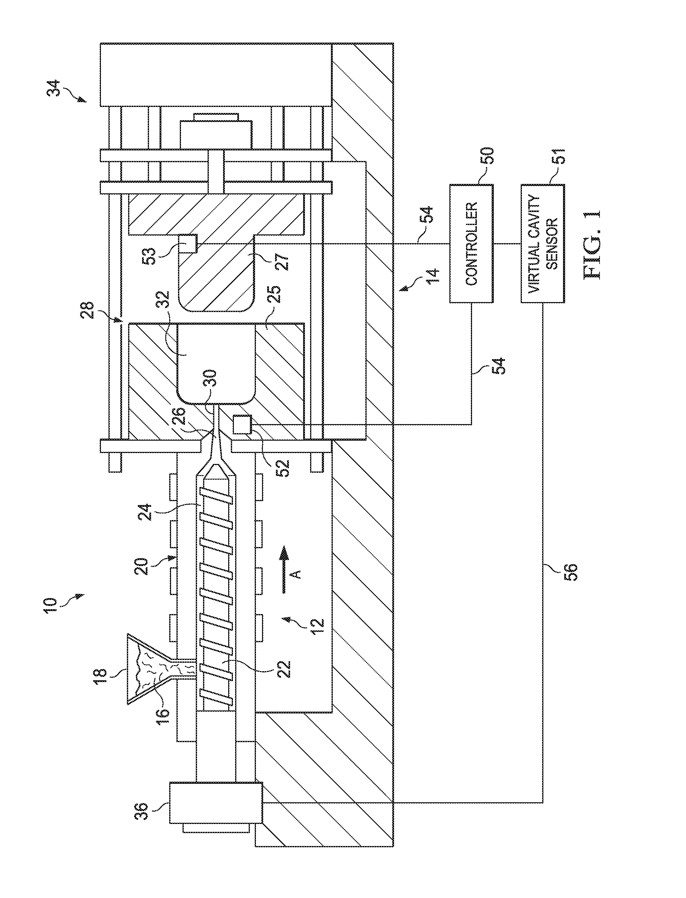
[0019]Referring to the figures in detail, FIG. 1 illustrates an exemplary injection molding apparatus 10 for producing thermoplastic parts in high volumes (e.g., a class 101 injection mold, or an “ultra-high productivity mold”, a class 102 (medium-to-high productivity mold), or class 103 (a medium productivity mold)). The injection molding apparatus 10 generally includes an injection system 12 and a clamping system 14. A thermoplastic material may be introduced to the injection system 12 in the form of thermoplastic pellets 16. The thermoplastic pellets 16 may be placed into a hopper 18, which feeds the thermoplastic pellets 16 into a heated barrel 20 of the injection system 12. The thermoplastic pellets 16, after being fed into the heated barrel 20, may be driven to the end of the heated barrel 20 by a ram, such as a reciprocating screw 22. The heating of the heated barrel 20 and the compression of the thermoplastic pellets 16 by the reciprocating screw 22 causes the thermoplastic ...


PUM

PropertyMeasurementUnit
Timeaaaaaaaaaa
Forceaaaaaaaaaa
Pressureaaaaaaaaaa

Abstract

A injection molding method involves measuring, using at least one strain gauge sensor, a change in strain in a mold side of a mold cavity, approximating a pressure within the mold cavity based on the change in strain, comparing the approximated pressure to a pre-set trigger point, and if the approximated pressure equals or exceeds the pre-set trigger point, activating a virtual cavity sensor having an optimal pre-defined pressure-time curve, wherein upon activation, the virtual cavity sensor tracks approximated pressures calculated from the change in strain measurements measured by the at least one strain gauge sensor over time and compares the results of the approximated pressure tracking to the optimal pre-defined pressure-time curve.

Description

FIELD OF THE INVENTION[0001]This application relates generally to injection molding and, more specifically, to methods for using a strain gauge on the exterior of a mold surface adjacent to a parting line of the mold to approximate conditions, such as pressure, within an injection mold and, if an approximated condition hits or exceeds a pre-set trigger point, perform additional calculations and / or adjust the injection molding process, thereby using the strain gauge along with a virtual cavity sensor as part of a pressure sensing system.BACKGROUND OF THE INVENTION[0002]During injection molding, molten thermoplastic material flows into a mold cavity of a mold via one or more gates. The pressure within the mold cavity is an important vector, as insufficient pressure may result in improperly formed parts while excessive pressure may result in damage to the mold. The pressure at the melt flow front provides information relevant to the injection molding process overall by, for example, en...

Claims


Application Information

Patent Timeline
IPC IPC(8): B29C45/77
CPCB29C45/77B29L2031/00B29K2101/12B29C45/76B29C45/766B29C2945/76006B29C2945/76267B29C2945/76381B29C2945/76481B29C2945/76498B29C2945/76765B29C2945/76859B29C2945/76933B29C2945/76943
Inventor POLLARD, RICK ALANRAKER, JOSHUA DOUGLASALTONEN, GENE MICHAELHANSON, III, H. KENNETH
Owner IMFLUX INC
Learn More