
Electrostatic metal porous body forming apparatus and electrostatic metal porous body forming method using the same

a technology of electrostatic metal and forming method, which is applied in the direction of electrostatic spraying apparatus, liquid spraying apparatus, coating, etc., can solve the problems of difficult to perform a forming process in a general open porous volume, difficult to achieve pvd or cvd coating process, and non-uniform coating of powder, etc., to achieve high efficiency, reduce environmental contamination, and speed up the effect of speed

Inactive Publication Date: 2017-01-26
ALANTUM CORP
View PDF0 Cites 1 Cited by
  • Summary
  • Abstract
  • Description
  • Claims
  • Application Information

AI Technical Summary

Benefits of technology

The invention is a machine and method for making a metal foam at high speed and efficiency, while reducing environmental contamination. It can also minimize the wasted amount of metal powder and make a uniform coating layer, resulting in better efficiency and quality of coating.

Problems solved by technology

However, in the case of using CVD, the metal powder is non-uniformly coated such that it is not easy to perform a forming process in a general open-porous volume.
The well-known PVD or CVD coating process is restricted in a depth of penetration into a porous foam structure, and may require a considerable manufacturing cost.

Method used


Image

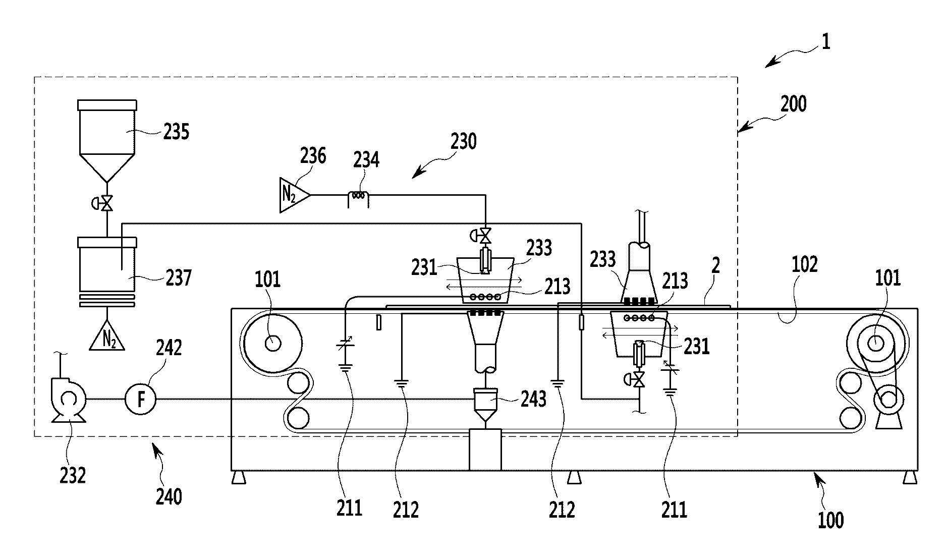
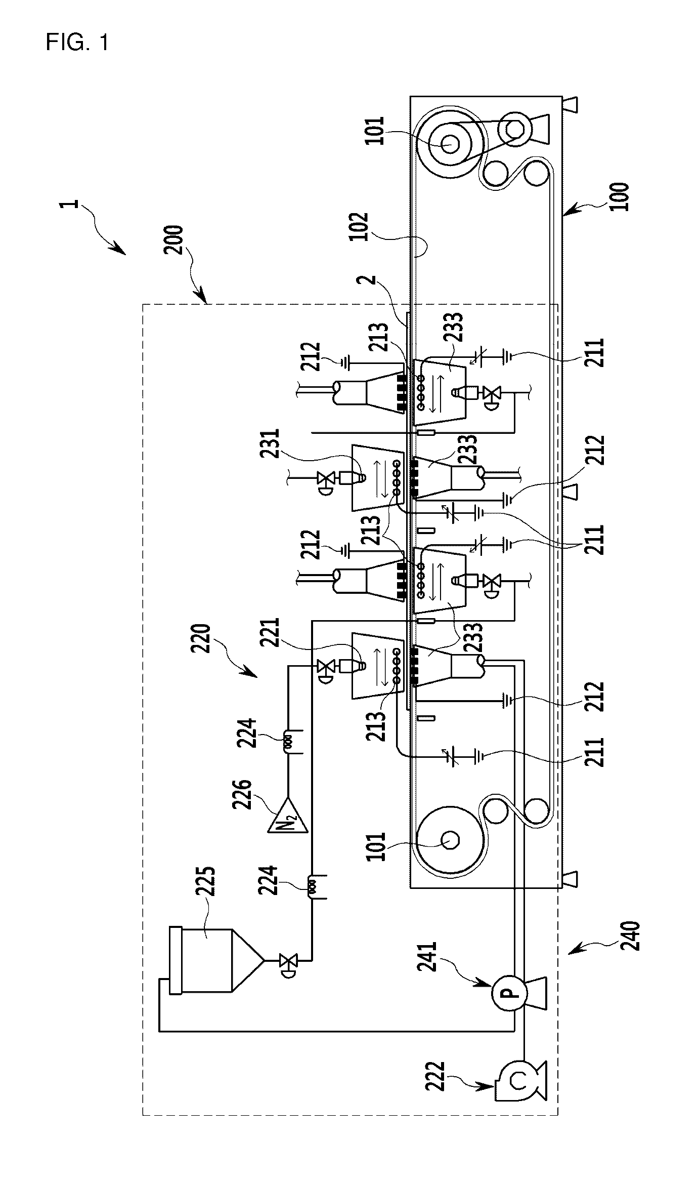
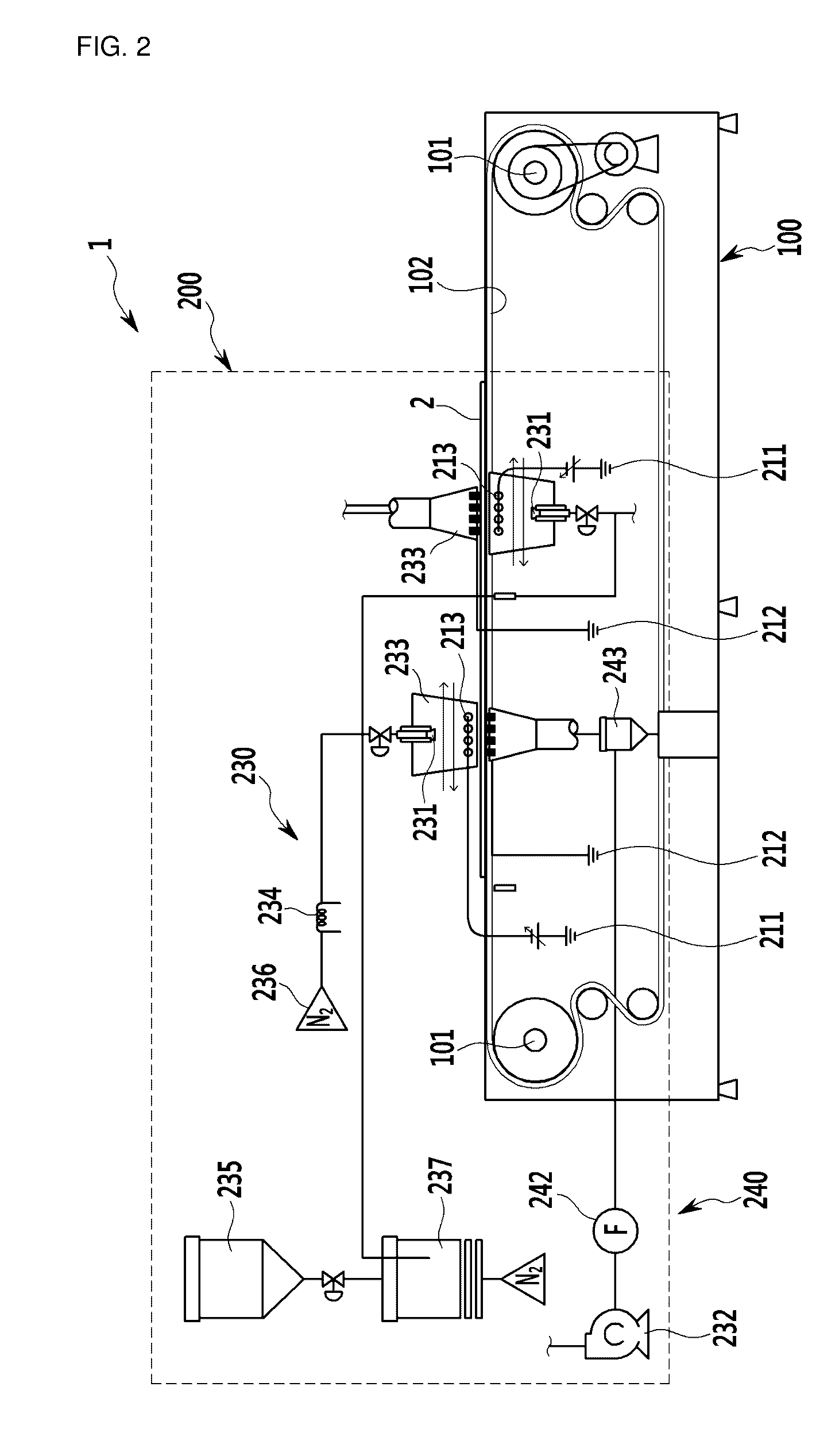
  • Electrostatic metal porous body forming apparatus and electrostatic metal porous body forming method using the same
  • Electrostatic metal porous body forming apparatus and electrostatic metal porous body forming method using the same
  • Electrostatic metal porous body forming apparatus and electrostatic metal porous body forming method using the same

Examples


example 1

Manufacturing Metal Porous Body

[0082]First, an Fe foam sheet substrate having a size of about 1520 mm×300 mm×1.9 mm and an average pore size of about 580 μm is prepared. Each foam sheet has a shape in which opposite horizontal edges are pressed, and each thickness of the pressed edges is about 2 mm. Further, the pressed portions of each foam sheet are formed to have a vertical width of about 10 mm from the horizontal opposite edges, and several pores are formed in the pressed portions at an interval of 10 mm. Each of the pores has a diameter of about 5 mm. This facilitates precise pitch transfer of the foam sheets and stable maintenance of the plane that is parallel with the ground.

[0083]Next, the Fe foam sheet substrate is fixed to the substrate supporter, and a transfer module enters the apparatus.

[0084]Subsequently, polyethylenimine is coated on each Fe foam sheet substrate transferred by the transfer module by using the binder supplier. The Fe foam sheet substrates coated with t...

example 2

Manufacturing Metal Porous Body

[0088]A metal porous body is manufactured by using the same method as Example 1, except for using a foam sheet substrate with a thickness of about 3.0 mm and a Ni foam sheet with an average pore size of about 1200 μm.

[0089]FIG. 7c is an enlarged photograph of a metal porous body manufactured in Example 2, and FIG. 7d is a photograph of an incision surface of the metal porous body manufactured in Example 2.

[0090]As a result, the Fe alloy powder is uniformly formed on the surface of the Ni foam sheet substrate.


PUM

PropertyMeasurementUnit
voltage magnitudeaaaaaaaaaa
voltageaaaaaaaaaa
particle sizeaaaaaaaaaa

Abstract

An exemplary embodiment of the present invention provides an electrostatic metal porous body forming apparatus including: a transfer module transferring a porous body substrate; and a coating module coating a metal powder on the porous body substrate, wherein the transfer module includes a substrate supporter fixing the porous body substrate while the porous body substrate is transferred, and wherein the coating module includes: an electrifier including a first electrode electrifying the metal powder, a second electrode facing the first electrode, a first power supplier connected with the first electrode supplying electricity to the first electrode, and a second power supplier connected with the second electrode supplying electricity electrified with an opposite charge to a charge caused by the electrification of the first electrode to the second electrode, and generating a pulse type of voltage; and a metal powder supplier including a metal powder vessel storing the metal powder therein and supplying the metal powder to the outside, and an outlet separately disposed above or below the porous body substrate injecting the metal powder, and transferring or injecting the metal powder that is electrified and coated by the electrifier.

Description

TECHNICAL FIELD[0001]This specification relates to an electrostatic metal porous body forming apparatus and an electrostatic metal porous body forming method using the same.BACKGROUND ART[0002]A porous body substrate having an open-cell structure may be coated with a metal powder containing an additional alloy component. Accordingly, its mechanical characteristic may be improved, while an effect such as separation or filtration may be lowered. Resultantly, surface roughness obtained from internal surfaces of fine pores and webs may be insufficient for a desired effect such as separation or filtration.[0003]To solve this problem, an adequate surface coating method may be performed. For example, chemical vapor deposition (CVD) or physical vapor deposition (PVD) may be performed. However, in the case of using CVD, the metal powder is non-uniformly coated such that it is not easy to perform a forming process in a general open-porous volume. The well-known PVD or CVD coating process is r...

Claims


Application Information

Patent Timeline
Patent Type & Authority Applications(United States)
IPC IPC(8): B05C19/04B05D1/00
CPCB05C19/04B05D2401/32B05D1/007B22F3/11B22F2999/00B05B5/005B05B5/0535B05B5/081B05B5/084B05B5/1683B05B7/1404B05B7/1454B05B7/1477B05B14/10B05B14/30Y02P70/10B22F5/006B22F3/003
Inventor CHOI, BYOUNG KWONLEE, CHANG WOOYU, SEUNG WOONPARK, MAN HOBAE, JUNG SUK
Owner ALANTUM CORP
Learn More