
Conductivity distribution derivation method and conductivity distribution derivation device

Active Publication Date: 2017-01-19
KOBE UNIV +1
View PDF3 Cites 12 Cited by
  • Summary
  • Abstract
  • Description
  • Claims
  • Application Information

AI Technical Summary

Benefits of technology

The patent describes a method and device that can inspect for electrical failures, such as short circuits, within batteries. By measuring the magnetic field and conductivity distribution, the method can accurately determine the conductivity distribution and effectively inspect for short circuits. Overall, this technology provides a reliable and efficient way to inspect batteries for electrical failures.

Problems solved by technology

In recent years, dendrites that grow in a lithium battery have been considered problematic because they may cause a short circuit within the battery, explosion of the battery, or the like.

Method used


Image

  • Conductivity distribution derivation method and conductivity distribution derivation device
  • Conductivity distribution derivation method and conductivity distribution derivation device
  • Conductivity distribution derivation method and conductivity distribution derivation device

Examples


embodiment

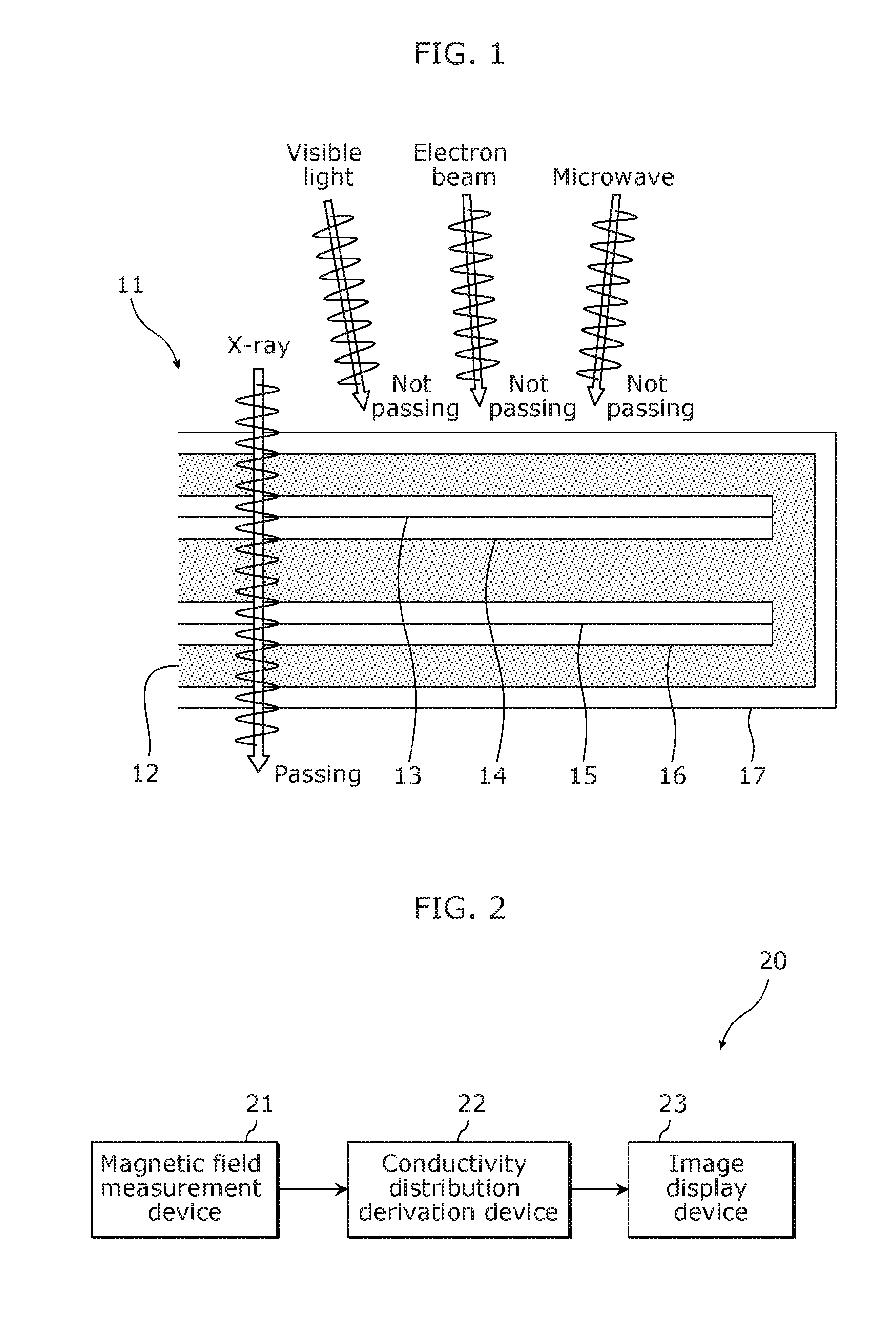
[0038]FIG. 1 illustrates a reference example of a battery inspection method. A battery 11 illustrated in FIG. 1 includes an electrolyte 12, an electric current collector 13, a positive electrode active material 14, a negative electrode active material 15, an electric current collector 16, and a metal package 17. The electrolyte 12, the electric current collector 13, the positive electrode active material 14, the negative electrode active material 15, and the electric current collector 16 are covered with the metal package 17.

[0039]Examples of a technical element used in non-destructive inspection include X-ray, visible light, electron beams, microwaves, and ultrasound waves. Among them, visible light, electron beams, and microwaves are not expected to be used for inspecting the battery 11 in a non-destructive manner because the transmittance of visible light, electron beams, and microwaves through the battery 11 is zero. High brightness X-ray can be used for inspecting the battery 1...

example 1

Extended Example 1

[0099]First, Extended example 1 is described. In Extended example 1, the derivation unit 32 of the conductivity distribution derivation device 22 determines a model for the conductivity distribution σ and a model for the electric potential distribution [Math. 36], and derives the x component Hx of the magnetic field vector and the y component Hy of the magnetic field vector on the basis of the model for the conductivity distribution σ and the model for the electric potential distribution [Math. 37].

φ  [Math. 36]

φ  [Math. 37]

The mode is also referred to as a candidate. When the derived x component Hx and y component Hy fit the magnetic field information obtained through the magnetic field measurement device 21 or the like, the derivation unit 32 determines a model for the conductivity distribution σ and a model for the electric potential distribution [Math. 38] as the conductivity distribution σ and the electric potential distribution [Math. 39].

φ  [Math. 38]

φ  [Mat...

example 2

Extended Example 2

[0111]Next, Extended example 2 is described. In Extended example 2, the derivation unit 32 of the conductivity distribution derivation device 22 derives the conductivity distribution σ according to a relational expression that allows the conductivity distribution σ to be derived directly from the magnetic field information. The relational expression that allows the conductivity distribution σ to be derived directly from the magnetic field information is derived from Expression 11. The following describes in detail the relational expression that is derived from Expression 11.

[0112]First, Expression 12 is derived by substituting [Math. 51] of the third equation in Expression 11 into the first terms on the right side of the first equation and the second equation in Expression 11.

[Math. 51]

σ(x,y)φ(x,y)

[Math. 52]

ΔHx=h2σ0∂y{∂x2φ+∂y2φ}δ(z−z0)−σ0h{∂yφ(x,y)}δ′(z−z0)

ΔHy=h2σ0∂x{∂x2φ+∂y2φ}δ(z−z0)−σ0h{∂xφ(x,y)}δ′(z−z0)   Expression 12

[0113]Next, Expression 14 is derived by the ...


PUM


Abstract

A conductivity distribution derivation method for deriving a conductivity distribution within a battery having an electrode plate that is flat includes: obtaining magnetic field information indicating a magnetic field; and deriving, based on a plurality of relational expressions which (i) an x component of a magnetic field vector in an x direction parallel to the electrode plate, (ii) a y component of the magnetic field vector in a y direction parallel to the electrode plate and perpendicular to the x direction, (iii) the conductivity distribution on a two-dimensional plane parallel to the electrode plate, and (iv) an electric potential distribution on a two-dimensional plane parallel to the electrode plate satisfy, the conductivity distribution that satisfies the plurality of relational expressions with respect to the magnetic field information.

Description

TECHNICAL FIELD[0001]The present invention relates to a conductivity distribution derivation method and a conductivity distribution derivation device for deriving a conductivity distribution within a battery.BACKGROUND ART[0002]In recent years, dendrites that grow in a lithium battery have been considered problematic because they may cause a short circuit within the battery, explosion of the battery, or the like. Therefore, effective inspection methods for preventing such a short circuit or the like have been researched and developed. In this regard, Patent Literature (PTL) 1 discloses a method for examining the condition of a battery by using high-brightness X-ray, visible light, or ultrasound waves.CITATION LISTPatent Literature[0003][PTL 1] Japanese Unexamined Patent Application Publication (Translation of PCT Application) No. 2012-524385SUMMARY OF INVENTIONTechnical Problem[0004]However, visible light and microwaves (magnetic resonance imaging: MRI) are less likely to pass throu...

Claims


Application Information

Patent Timeline
IPC IPC(8): G01R31/36
CPCG01R31/3651G01R31/3662G01R31/389G01N27/72G01R31/367G01R31/385
Inventor KIMURA, KENJIROKIMURA, NORIAKI
Owner KOBE UNIV
Learn More