Data output device and method, and non-transitory computer readable medium

Inactive Publication Date: 2017-01-19
FUJIFILM CORP
View PDF3 Cites 9 Cited by
  • Summary
  • Abstract
  • Description
  • Claims
  • Application Information

AI Technical Summary

Benefits of technology

The present invention enables us to easily recognize both important points in an image regarding medical care and changes in time series data at those points.

Problems solved by technology

Since the trend screen has a longer time scale, it is easy to recognize a summary such as a trend of a transition of the inspection value, but it is difficult to recognize a detailed change in the inspection value.
On the other hand, since the current screen has a shorter time scale, it is easy to recognize the detailed change in the inspection value, but it is difficult to recognize the summary of the transition of the inspection value.
However, since the second display screen is an area in which only the summary is displayed and the time scale is long, the indicator can only be assigned to a rough period.
Therefore, for example, it is not possible to deal with a demand in a medical field for assignment of an indicator as a pinpoint to, for example, a sudden change point of the measurement value by referring to a daily change of a measurement value measured every day such as blood pressure.
However, there is a problem in that the risk of oversight of the indicator assigned in the past of the time-series data cannot be reduced only by the assignment of the indicator to the first display screen.
This is because, although in the case of, for example, a patient visiting a hospital for a long period, time-series data is accumulated over a long period of time, all data of the time-series data cannot be displayed since a display range of the time-series data is limited in the first display screen having a shorter time scale than the second display screen.
However, on the other hand, it is not realistic that a busy doctor remembers all places to which the indicators attached by the doctor.
Accordingly, since the risk of the oversight correspondingly increases, such a case is particularly problematic.

Method used


Image

  • Data output device and method, and non-transitory computer readable medium
  • Data output device and method, and non-transitory computer readable medium
  • Data output device and method, and non-transitory computer readable medium

Examples


first embodiment

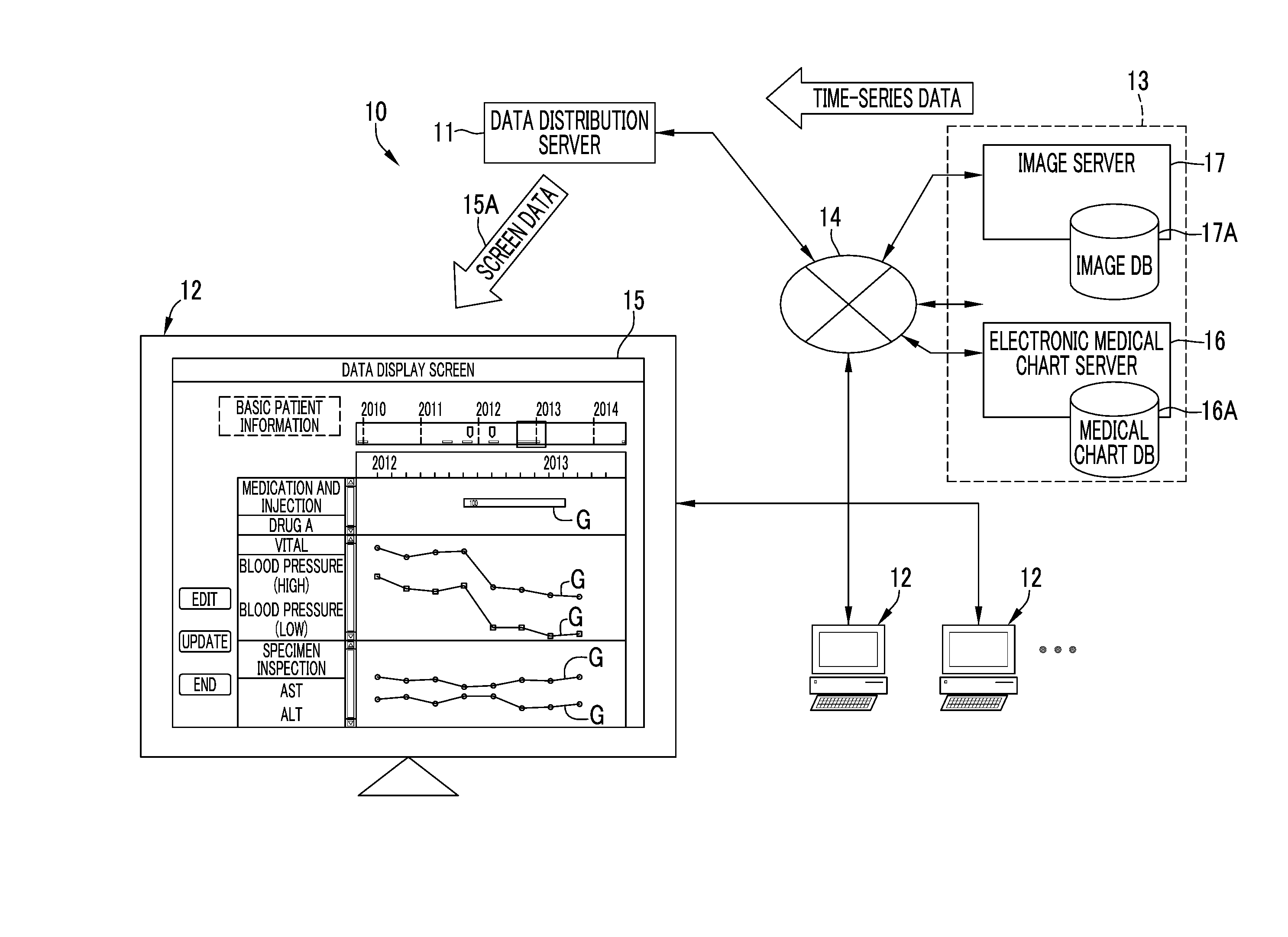
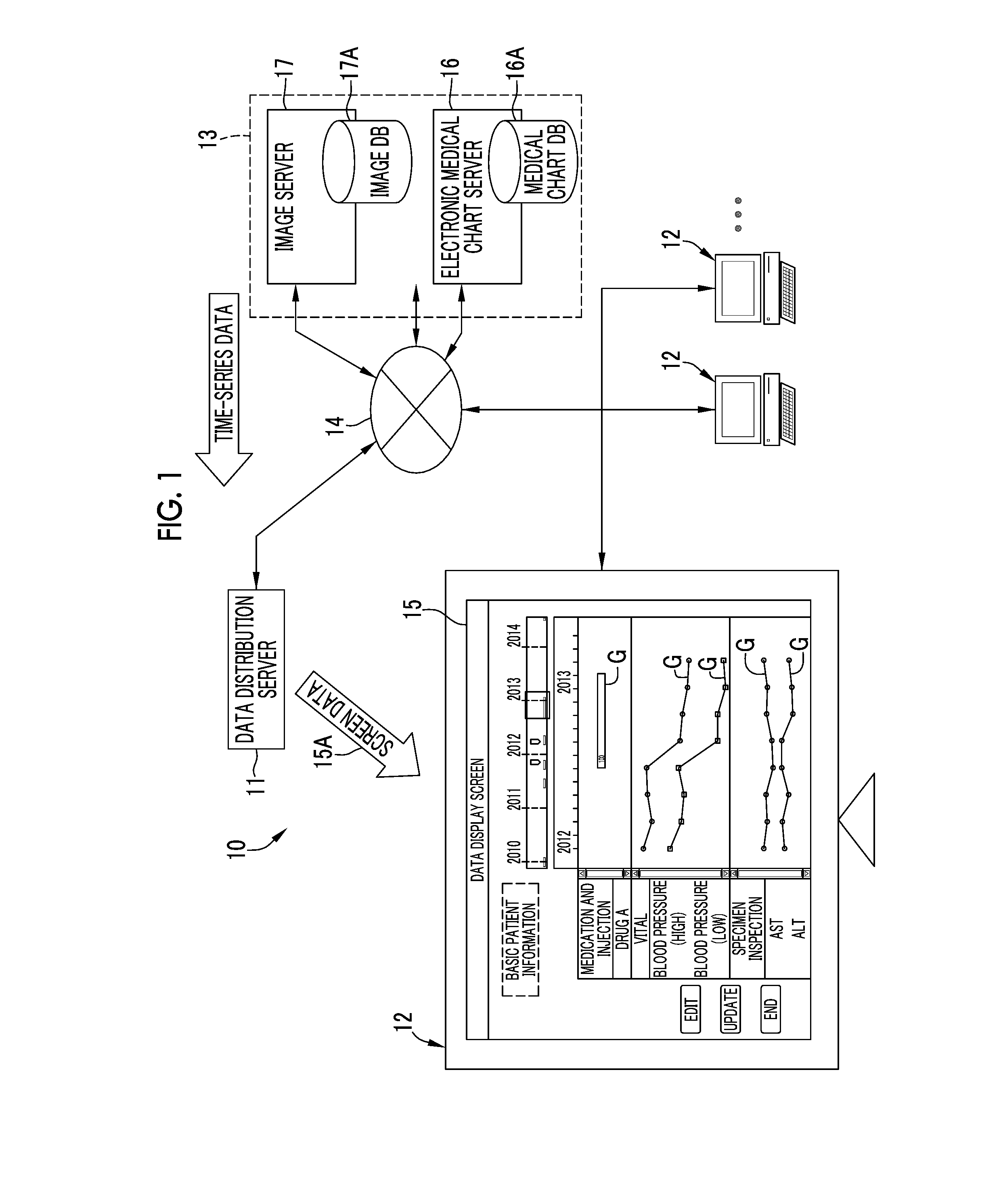
[0058]A medical information system 10 illustrated in FIG. 1 is a computer system that is used to manage information on medical care at a medical facility such as a hospital. This medical information system 10 includes a data distribution server 11, a client terminal 12, a server group 13, and a network 14 that connects the components so that the components can communicate with each other. In the server group 13, an electronic medical chart server 16, and an image server 17 are included. The network 14 is, for example, a local area network (LAN) that is laid in a hospital.

[0059]The client terminal 12 is a terminal that is installed in respective medical care departments such as an internal medicine, a surgery, an otolaryngology, and ophthalmology and is operated, for example, by a doctor in the medical care department. The client terminal 12 has a function of accessing the electronic medical chart server 16 and inputting and viewing electronic medical charts. Medical care information...

second embodiment

[0136]A second embodiment illustrated in FIGS. 15 to 17 is an embodiment in which a degree of importance can be set for at least one of first and second indicators. Other points are the same as those of the first embodiment, and a difference will be described hereinafter. As illustrated in FIG. 15, a degree-of-importance designation portion 89A for designating a degree of importance is provided in an indicator setting screen 89 of the second embodiment.

[0137]In the degree-of-importance designation portion 89A, for example, a radio button for designating a degree of importance of two steps including “high” and “normal” by an operation of the pointer 36 is provided. The first indicator 56A in a case in which “normal” is designated and the first indicator 56B in a case in which “high” is designated have different display modes, and one of the first indicator 56A and 56B is selected according to a designation of the degree of importance. In the first indicator 56B in which the degree of...

third embodiment

[0143]A third embodiment illustrated in FIG. 18 is an embodiment in which the second display period of the second display area 42 can be set according to a period in which there is the first indicator 56. For example, assuming that a point in time at which the data display screen 15 is displayed in the client terminal 12 is a current point in time T0, the period in which there is the first indicator 56 is extracted from among predetermined period that is most recent from the current point in time T0. In this example, the current point in time T0 is March 2014, and the most recent predetermined period is about 3 years. From this, the period in which there is the first indicator 56 is extracted as an indicator presence period. In this example, the second indicator 57 is present in 2010, but this period is outside the predetermined period, and accordingly, is not included in the indicator presence period to be extracted. The extracted indicator presence period is set as the second disp...


PUM


Abstract

A data output device capable of simply performing both of recognition of an entire image at an important point in time regarding medical care and recognition of a detailed change in time series data at the point in time is provided.A data display screen includes first and second display areas. In the first display area, time-series data indicating a state transition of a patient or content related to medical care performed on the patient is displayed in a graph. First indicators can be assigned to the graph. Second indicators are displayed at corresponding positions in the second display area that temporally correspond to designated positions in the first display area to which the first indicators are assigned. A second time axis in the second display area has a time scale which is longer than that of a first time axis in the first display area.

Description

CROSS-REFERENCE TO RELATED APPLICATION[0001]This application is a Continuation of PCT International Application PCT / JP2015 / 057932 filed on 17 Mar. 2015, which claims priority under 35 USC 119(a) from Japanese Patent Application No. 2014-074276 filed on 31 Mar. 2014. The above application is hereby expressly incorporated by reference, in its entirety, into the present application.BACKGROUND OF THE INVENTION[0002]1. Field of the Invention[0003]The present invention relates to a data output device and a data output method that output time-series data regarding medical care, and a non-transitory computer readable medium.[0004]2. Description of the Related Art[0005]In recent years, various medical care information acquired in medical care of a patient has been stored and managed as electronic data using a computer system. In the medical care information, for example, measured values of vital signs such as a heart rate, a pulse rate, blood pressure, and body temperature, inspection values...

Claims


Application Information

Patent Timeline
IPC IPC(8): A61B5/00G09G5/18G09G5/00A61B5/0205G06F19/00G16H10/60
CPCA61B5/7425A61B5/02055A61B5/4836G06F19/3406G09G5/006G09G5/18G06F3/0485A61B5/021A61B5/0816G09G2380/08G06F3/0482G06T11/206G06F2203/04803A61B5/024A61B5/00G06Q10/10G16H15/00G16H20/10G16H40/63G16H40/67G06F3/048G16H10/60
Inventor TSUGO, AKINARI
Owner FUJIFILM CORP
Why Eureka
Try Eureka