Armature of electric motor

Active Publication Date: 2019-11-21
MITSUBISHI ELECTRIC CORP
View PDF0 Cites 1 Cited by
  • Summary
  • Abstract
  • Description
  • Claims
  • Application Information

AI Technical Summary

Benefits of technology

The present invention aims to provide an improved electric motor with a new configuration for the insulating holder. This new configuration allows for a more compact motor design and simplifies the assembly and management processes. Additionally, the invention guarantees that the insulating holder does not require a specific distance between bus bars to ensure proper insulation. This allows for a more efficient and cost-effective electric motor design, regardless of its voltage capacity.

Problems solved by technology

However, a paste process of the insulating sheet is increased for the components, and an enormous load is required in order to manage a crease and an inclination of the pasted sheet.

Method used


Image

  • Armature of electric motor
  • Armature of electric motor
  • Armature of electric motor

Examples


embodiment 1

[0029]Hereinafter, an armature of an electric motor according to Embodiment 1 of the present invention will be explained by using FIG. 1 through FIG. 10. In each of FIG. 1 through FIG. 10, the same reference symbols are given to the same or equivalent parts.

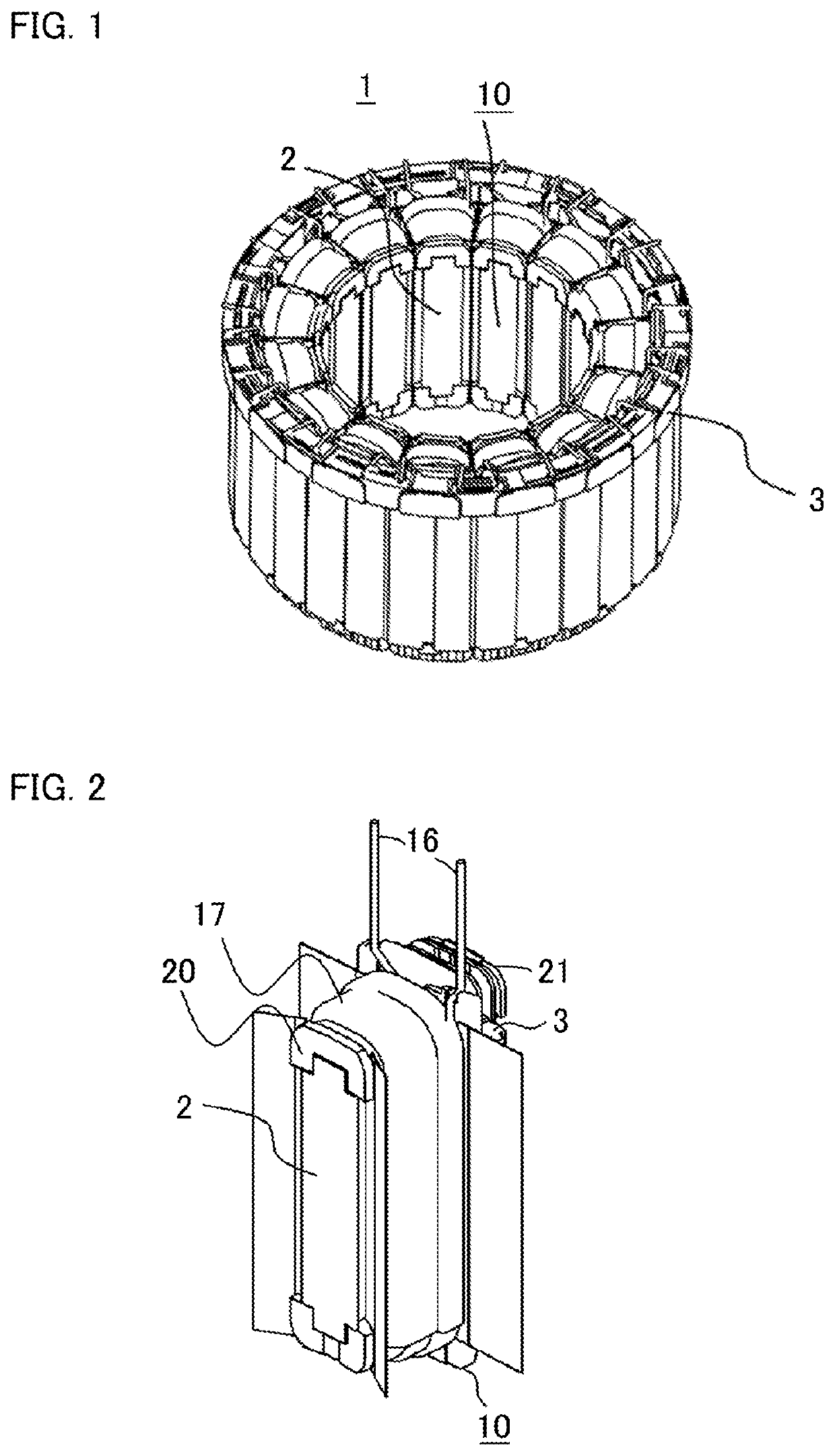
[0030]FIG. 1 is an oblique perspective view which indicates an armature (a stator) 1 of a three-phase brushless motor according to Embodiment 1. The armature 1 is totally configured in an annular shape, and a rotor (which is not illustrated) is arranged, with a predetermined distance, at an inner circumference side of the armature 1.

[0031]The armature 1 is configured in such a way that a plurality of steel sheets are laminated, and the armature 1 is composed of a plurality of armature cores 10 which are radially arranged in parallel with equal pitches in a circumference direction, and each of the armature cores 10 is composed of each of teeth 2, which is protruded toward an inner circumference side, and a yoke 3 by which each of ...

embodiment 2

[0045]Hereinafter, an armature of an electric motor according to Embodiment 2 of the present invention will be explained by using FIG. 11 through FIG. 12. In each of FIG. 11 through FIG. 12, the same reference symbols are given to the same or equivalent parts. Embodiment 2 shows a deformation example of an insulating cap 40. The insulating cap 40, according to, which is indicated in FIG. 11, is formed in an annular shape of one circle, and insulating walls 41 are provided with an equal distance at the insulating cap 40. Moreover, a flange 44 is provided at an outer shape side, and attaching holes 45 are provided.

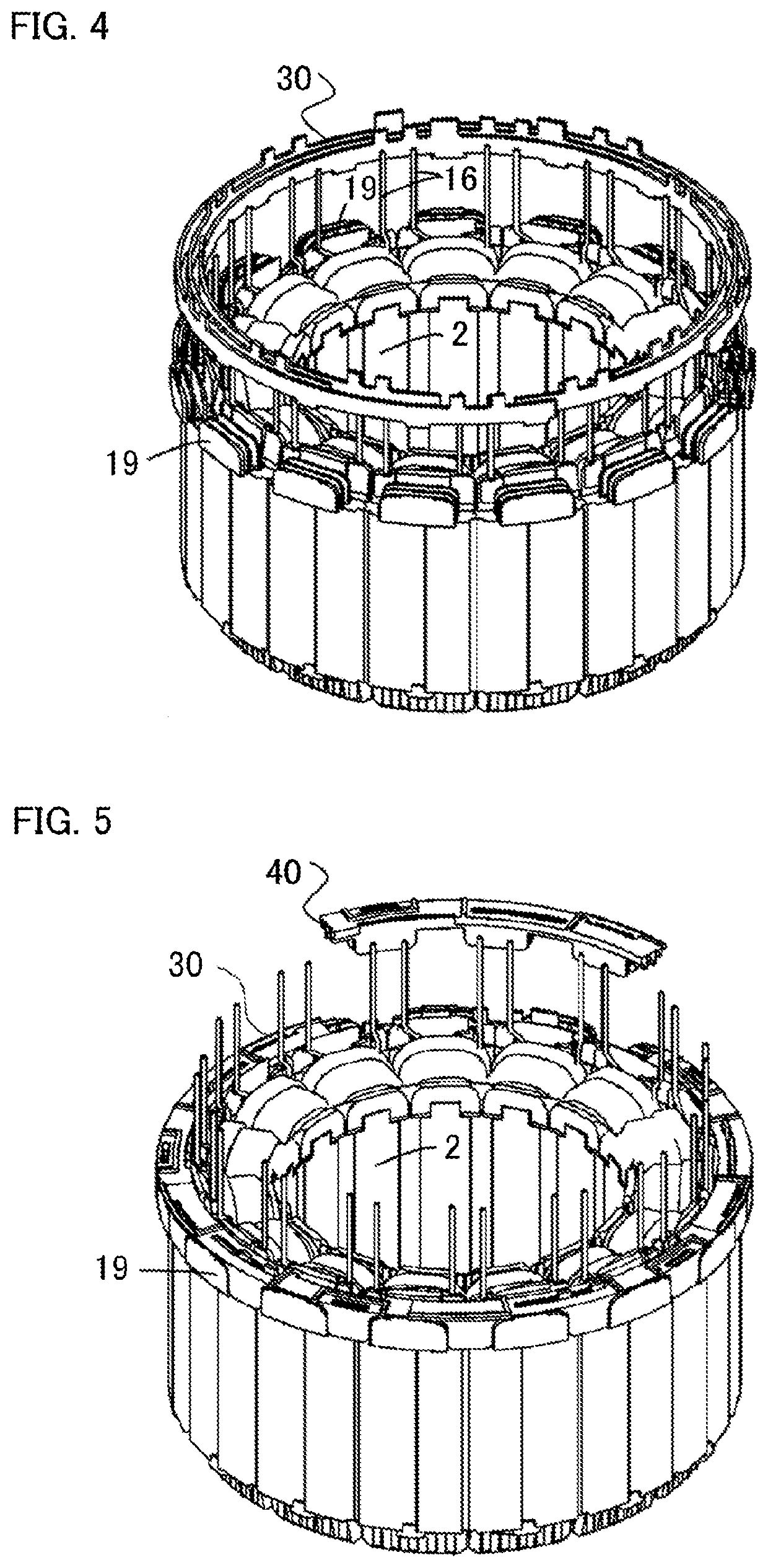
[0046]As indicated FIG. 12, an assembling process of an armature 1 according to Embodiment 2, in which the insulating cap 40, which is indicated in FIG. 11, is inserted from a shaft direction of the armature 1 to bus bars 30, which are arranged in an annular shape, by using a similar way which is indicated in FIG. 5 according to Embodiment 1, in a state where upper and lower...


PUM


Abstract

An insulating holder is comprised of a bobbin portion and bus bar supporting portions, and the bus bar supporting portions have bus bar walls which electrically separate each of bus bars, and step portions are formed, in a lamination direction of the bus bars, at the bus bar walls, and gap portions are formed, between the bus bars and the bus bar walls, in a longitudinal direction of the bus bars and in a lamination direction of cores, at the step portion, and an insulating cap, which complements the gap portions from the outside and maintains the bus bars, is included, in a state where the bus bars are installed to the bus bar walls.

Description

BACKGROUND OF THE INVENTIONField of the Invention[0001]The present invention relates to an armature of an electric motor, and more particularly, relates to an armature structure of an electric motor which includes an insulating holder by which portions between each of a plurality of bus bars arranged at the outside of armature cores, and a coil wound around the armature cores, are insulated and maintained.Description of the Related Art[0002]For example, a three-phase AC motor such as a three-phase brushless motor and a three-phase linear motor is comprised of an armature, in which a plurality of armature cores composed of laminated steel sheets, are arranged in parallel, and a movable element (a rotor) faced to the armature and similarly composed of laminated steel sheets. Moreover, the armature cores are comprised of coils wound around an outer circumference of a teeth portion of the armature cores, and an insulating holder by which a plurality of bus bars which are laminated in an...

Claims


Application Information

Patent Timeline
IPC IPC(8): H02K3/38H02K3/52
CPCH02K2203/12H02K2203/09H02K3/38H02K3/522H02K3/50H02K1/148
Inventor KITTA, YOSHIAKITSUIKI, HIRONORI
Owner MITSUBISHI ELECTRIC CORP
Why Eureka
Try Eureka