Chromatic range sensor including dynamic intensity compensation function
- Summary
- Abstract
- Description
- Claims
- Application Information
AI Technical Summary
Benefits of technology
Problems solved by technology
Method used
Image
Examples
Embodiment Construction
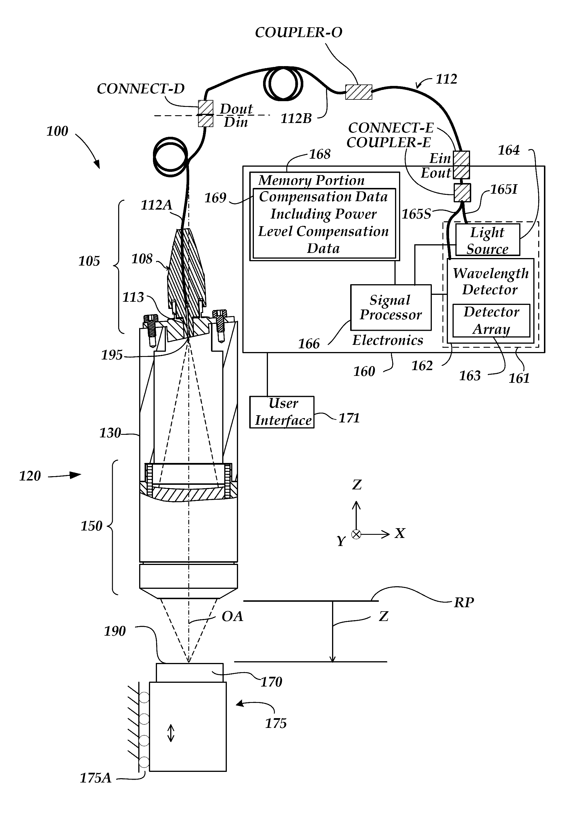
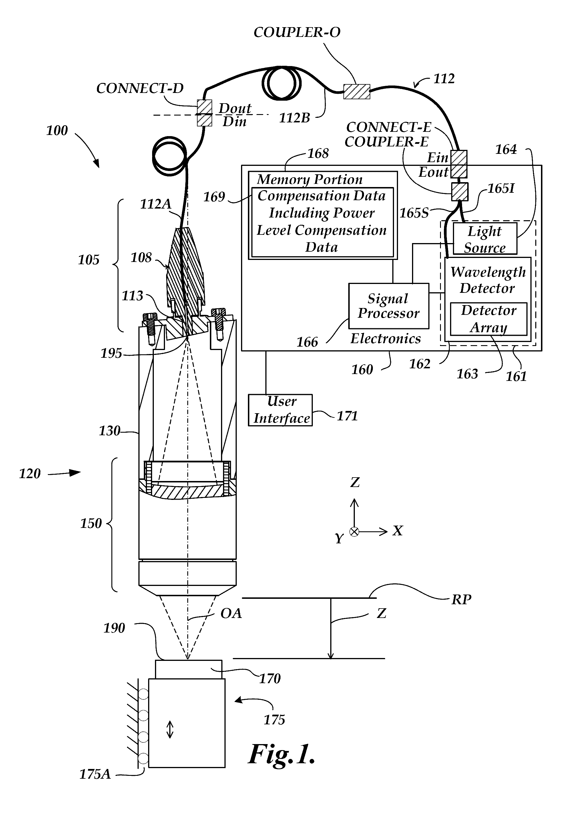
[0025]FIG. 1 is a block diagram of one exemplary embodiment of a chromatic range sensor (CRS) system 100, including an optical element 120 (e.g., an optical pen), an electronics portion 160, and a user interface portion 171. The embodiment of the electronics portion 160 includes a signal processor 166, a memory portion 168 and a source and detector subsystem 161 comprising a wavelength detector 162 and a broadband light source 164. The CPS system 100 shown in FIG. 1 is a chromatic point sensor (CPS) system which measures a single measurement point at a time. In various embodiments, the wavelength detector 162 includes a detector array 163 of a spectrometer. The detector array 163 may comprise a plurality of pixels distributed along a measurement axis of the wavelength detector 162, wherein the plurality of pixels receive respective wavelengths and provide output spectral profile data. The electronics portion 160 is coupled to the optical element 120 through an optical path including...
PUM
 Abstract
Description
Claims
Application Information
 - R&D
- Intellectual Property
- Life Sciences
- Materials
- Tech Scout
- Unparalleled Data Quality
- Higher Quality Content
- 60% Fewer Hallucinations
Browse by: Latest US Patents, China's latest patents, Technical Efficacy Thesaurus, Application Domain, Technology Topic, Popular Technical Reports.
© 2025 PatSnap. All rights reserved.Legal|Privacy policy|Modern Slavery Act Transparency Statement|Sitemap|About US| Contact US: help@patsnap.com


