
Engine device

Active Publication Date: 2017-01-12
YANMAR POWER TECHNOLOGY CO LTD
View PDF2 Cites 2 Cited by
  • Summary
  • Abstract
  • Description
  • Claims
  • Application Information

AI Technical Summary

Benefits of technology

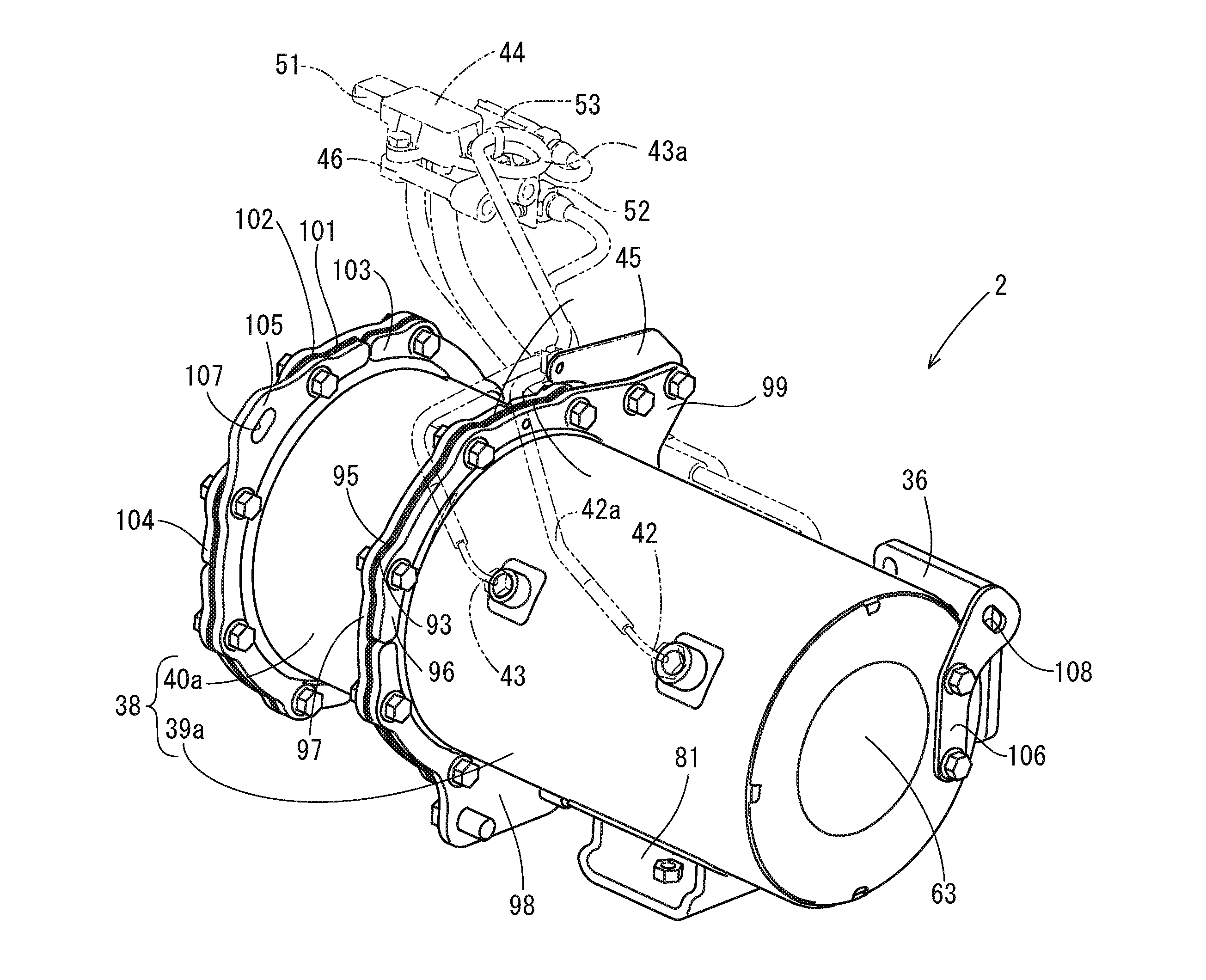
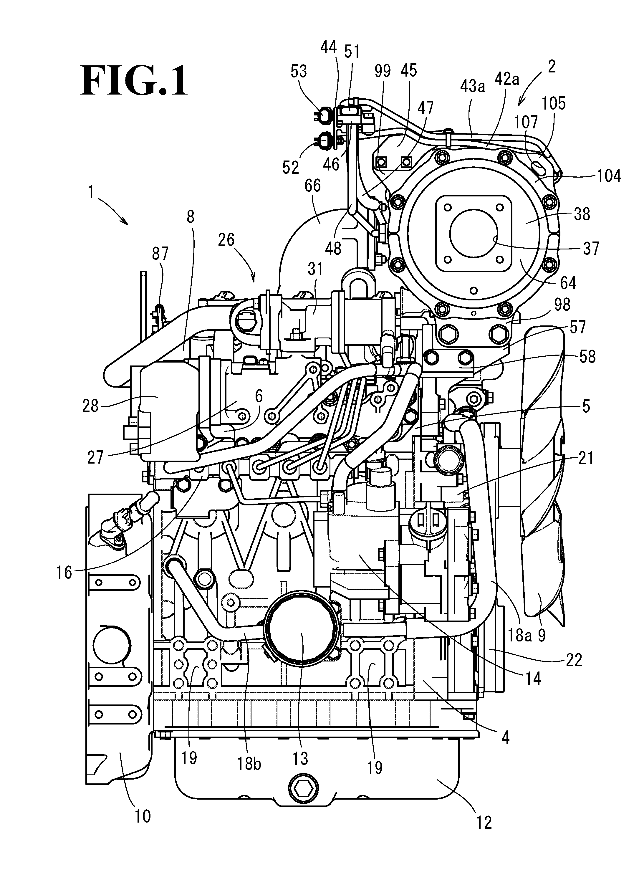
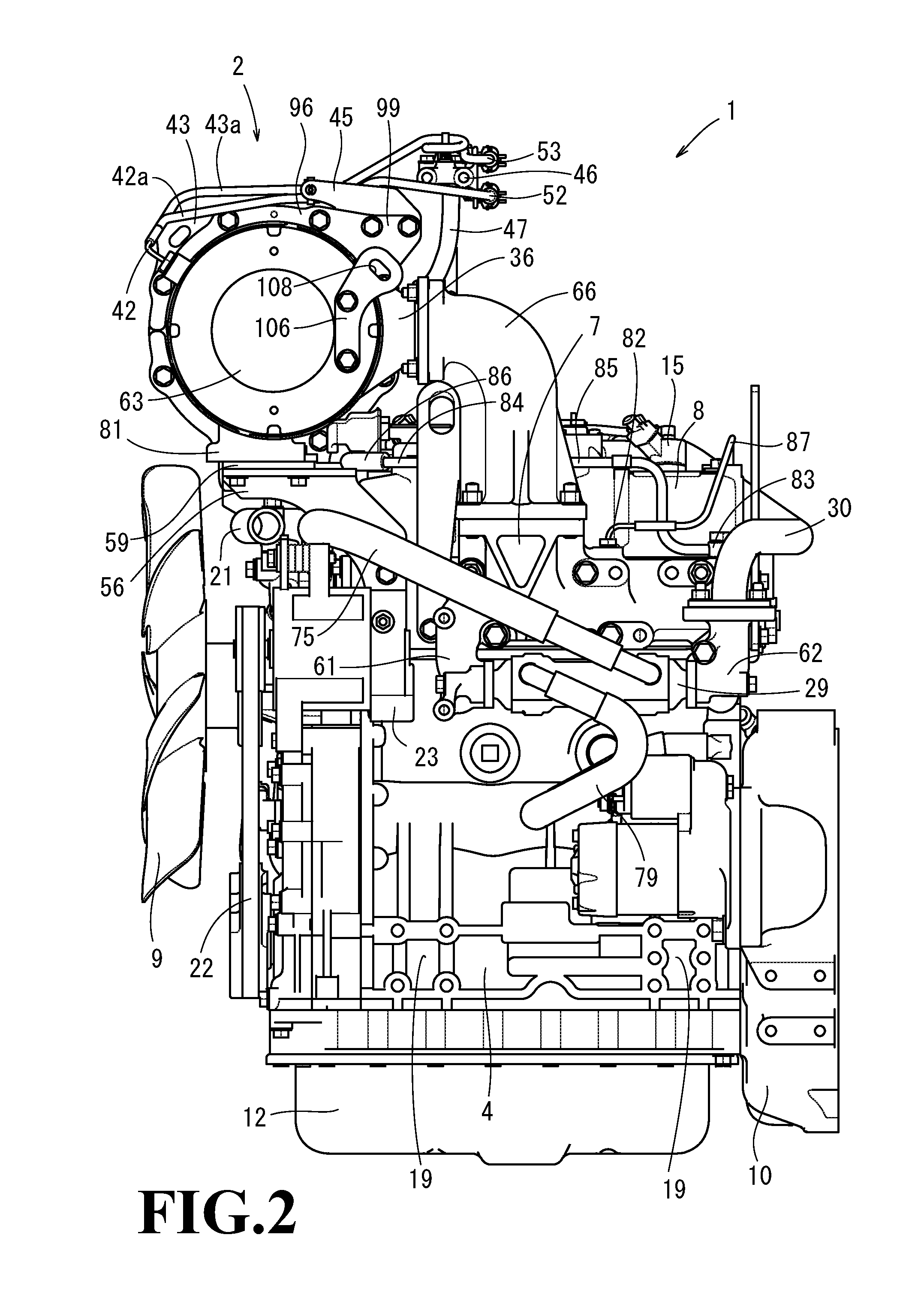
This patent is about an engine device with an exhaust gas purification device and electric parts that detect the state of the purification device. The electric parts are placed outside the purification device to reduce heat from the engine and purification device, and to prevent the parts from breaking down due to heat. The purification device is connected to the engine's exhaust manifold, and the electric parts are positioned away from the purification device to reduce heat influence. The patent also describes a cooling fan and a support system for the purification device, which provides rigidity and prevents damage from vibration. Overall, the technical effects of the patent are to reduce heat influence, prevent breakdown of electric parts, and facilitate maintenance work on the engine.

Problems solved by technology

As a result, even if a support structure for the muffler in the construction machine disclosed in Japanese Unexamined Patent Publication No. 2007-182705 is diverted to a support structure for the exhaust gas purification device, there is a problem that the exhaust gas purification device can not be stably assembled.
As a result, there is a risk that the electric parts attached to the exhaust gas purification device break down due to the heat from the exhaust gas purification device and the engine.
Particularly, in the case that the breakdown of the temperature sensor and the pressure sensor is generated, a state of the exhaust gas purification device can not be checked out.
As a result, a defect such as occurrence of engine stall is generated without dissolving the clogging in the device.

Method used


Image

  • Engine device
  • Engine device
  • Engine device

Examples


Embodiment Construction

[0033]A description will be given below of an embodiment of an engine device according to the present invention and a working machine having the engine device with reference to FIGS. 1 to 17. In the following description, a working vehicle is exemplified as the working machine according to the present embodiment, and details of its structure will be described. Further, in the following description, both side portions along an output shaft (a crank shaft) 3 (both side portions across the output shaft 3) are called as right and left sides, a side where a cooling fan 9 is arranged is called as a front side, a side where a flywheel 11 is arranged is called as a rear side, a side where an exhaust manifold 7 is arranged is called as a left side, and a side where an intake manifold 6 is arranged is called as a right side, and they are assumed to be references for positional relationship in four directions, and upward and downward directions in a diesel engine 1, for convenience.

[0034]First...


PUM


Abstract

An engine is provided with an exhaust gas treatment device which treats exhaust gas. The exhaust gas treatment device is provided with electric parts which detect a state of the exhaust gas purification device. The engine is provided with a cooling water circulation mechanism which circulates cooling water for the engine. Further, the electric parts are arranged in an outer side of the exhaust gas purification device on an extension in a longitudinal direction of the exhaust gas purification device.

Description

CROSS-REFERENCE TO RELATED APPLICATIONS[0001]The present application is a continuation application of International Application No. PCT / JP2015 / 56378, filed Mar. 4, 2015, which claims priority to Japanese Patent Application No. 2014-56917, filed Mar. 19, 2014. The contents of these applications are incorporated herein by reference in their entirety.BACKGROUND OF THE INVENTION[0002]The present invention relates to an engine device.[0003]Conventionally, there has been developed a technique that an exhaust gas purification device (a diesel particulate filter) is provided in an exhaust channel of an engine and exhaust gas discharged out of the diesel engine is purification treated by an oxidation catalyst or a soot filter in the exhaust gas purification device (for example, refer to Japanese Unexamined Patent Publication No. 2000-145430). Further, in recent years, in a field of a working machine such as a construction machine, an agricultural machine, and the like, it has been required t...

Claims


Application Information

Patent Timeline
IPC IPC(8): F01N11/00F01N13/00F02F1/24F01P5/02F01N3/035F01N3/10
CPCF01N11/005F01N3/035F01N3/103F02F1/24F01N2900/1602F01N13/008F01N2570/10F01N2570/12F01P5/02F01N3/021F01N3/106F01N11/002F01N13/18F01N2240/02F01N2340/04F01N2560/06F01N2560/08F01N2590/08F02D2200/0802F02D2200/0812F02D2400/22F01N13/0097Y02T10/40Y02T10/12
Inventor KUSAKA, HOKUTOMIYAZAKI, KAZUYUKI
Owner YANMAR POWER TECHNOLOGY CO LTD
Learn More