Fuel cell system

a fuel cell and system technology, applied in secondary cells, battery/fuel cell control arrangement, battery servicing/maintenance, etc., can solve the problems of difficult to open the valve in the frozen state, interfere with the start of the fuel cell system, and simple valve-opening and valve-closing operations are unlikely to eliminate the frozen state. , to prevent the state of charge of the secondary battery from being excessively decreased, the effect of increasing the pressure in the supply flow path

Active Publication Date: 2016-12-29
TOYOTA JIDOSHA KK
View PDF1 Cites 4 Cited by
  • Summary
  • Abstract
  • Description
  • Claims
  • Application Information

AI Technical Summary

Benefits of technology

[0009]The fuel cell system of this aspect causes the torque in the valve-opening direction and the torque in the valve-closing direction to be alternately applied to the motor-operated valve in the frozen state. The first drive pulse has the lower pulse speed than the second drive pulse, so that the torque in the direction of increasing the valve opening is larger than the torque in the direction of decreasing the valve opening, based on the characteristic of the stepping motor. This increases the likelihood that the frozen state is eliminated by the torque in the direction of increasing the valve opening. Additionally, inputting the second drive pulse into the stepping motor that is provided in the motor-operated valve in the frozen state generates the torque in the direction of decreasing the valve opening. The torque generated by the stepping motor is varied at the frequency that depends on the pulse speed of the drive pulse. Application of this vibration to the motor-operated valve in the frozen state is more likely to eliminate the frozen state. The second drive pulse has the higher pulse speed than the first drive pulse. This increases the frequency of the torque variation by the second drive pulse. This makes it more likely to eliminate the frozen state.
[0011]I the fuel cell system of the above aspect, the first drive pulse may be a pulse that provides a larger valve opening than a valve opening corresponding to an effective sectional area of zero between a valve seat and a valve element in the first motor-operated valve or in the second motor-operated valve. In the fuel cell system of this aspect, inputting the first drive pulse into the stepping motor provided in the motor-operated valve in the frozen state increases the likelihood that the effective sectional area becomes larger than zero when the frozen state is eliminated.
[0012]In the fuel cell system of the above aspect, the second drive pulse may be a pulse that provides a smaller valve opening than a valve opening corresponding to an effective sectional area of zero between a valve seat and a valve element in the first motor-operated valve or in the second motor-operated valve. In the fuel cell system of this aspect, inputting the second drive pulse into the stepping motor provided in the motor-operated valve in the frozen state makes the valve element more likely to abut on the valve seat and thereby makes it more likely to eliminate the frozen state. The valve element is likely to abut on the valve seat in the motor-operated valve in the frozen state, when the motion of the valve element is limited in the frozen state but the valve element is slightly movable.
[0014]In the fuel cell system of the above aspect, the first motor-operated valve may comprise a mechanism configured as a flow dividing valve. The fuel cell system may further comprise a bypass that is arranged to connect the first motor-operated valve with the discharge flow path. The discharge flow path may be connected with the bypass at a position downstream of the second motor-operated valve. The fuel cell system may be stopped in a state that the first motor-operated valve makes the supply flow path communicate with the bypass. Even when the compressor is driven in the state that the first motor-operated valve is frozen, this configuration causes the compressed air to be discharged to the atmosphere and thereby prevents the pressure in the supply flow path from being excessively increased.
[0015]The fuel cell system of the above aspect may further comprise a secondary battery that is configured to accumulate electric power generated by the fuel cell and supply the accumulated electric power to the first motor-operated valve, the second motor-operated valve and the controller to perform the predetermined process. The controller may stop the predetermined process when a state of charge of the secondary battery becomes lower than a reference value. This configuration prevents the state of charge of the secondary battery from being excessively decreased.
[0017]In the fuel cell system of the above aspect, the first drive pulse input into the first stepping motor and the first drive pulse input into the second stepping motor may have different pulse speeds, and the second drive pulse input into the first, stepping motor and the second drive pulse input into the second stepping motor may have different pulse speeds. This configuration respectively provides adequate drive pulses for the first motor-operated valve and the second motor-operated valve.

Problems solved by technology

It is difficult to open the valve in the frozen state.
This is likely to interfere with starting the fuel cell system.
In the case of a motor-operated valve that is controlled to be opened and closed by a stepping motor, on the other hand, the simple valve-opening and valve-closing operations are unlikely to eliminate the frozen state.

Method used


Image

  • Fuel cell system
  • Fuel cell system
  • Fuel cell system

Examples


Embodiment Construction

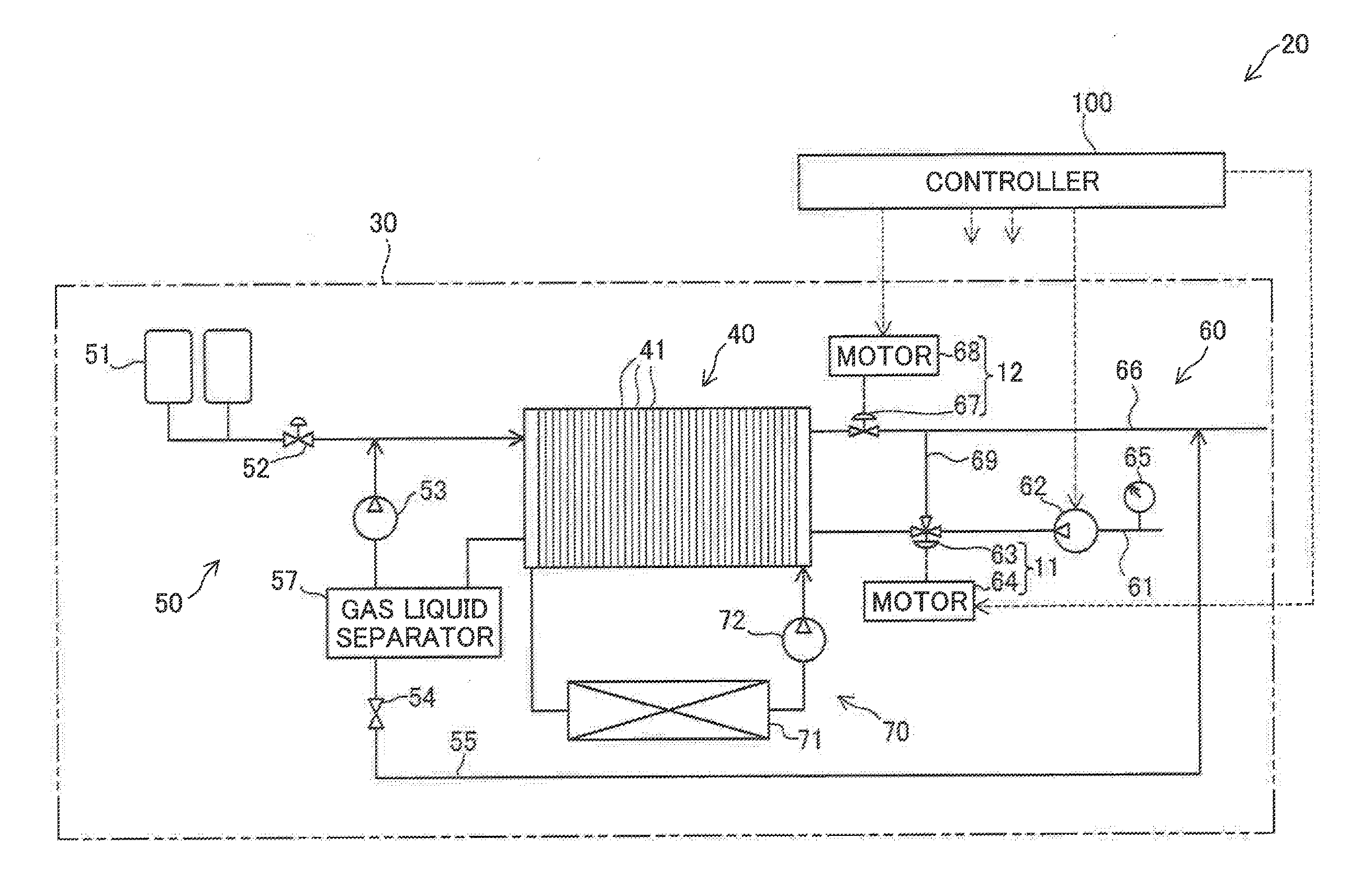
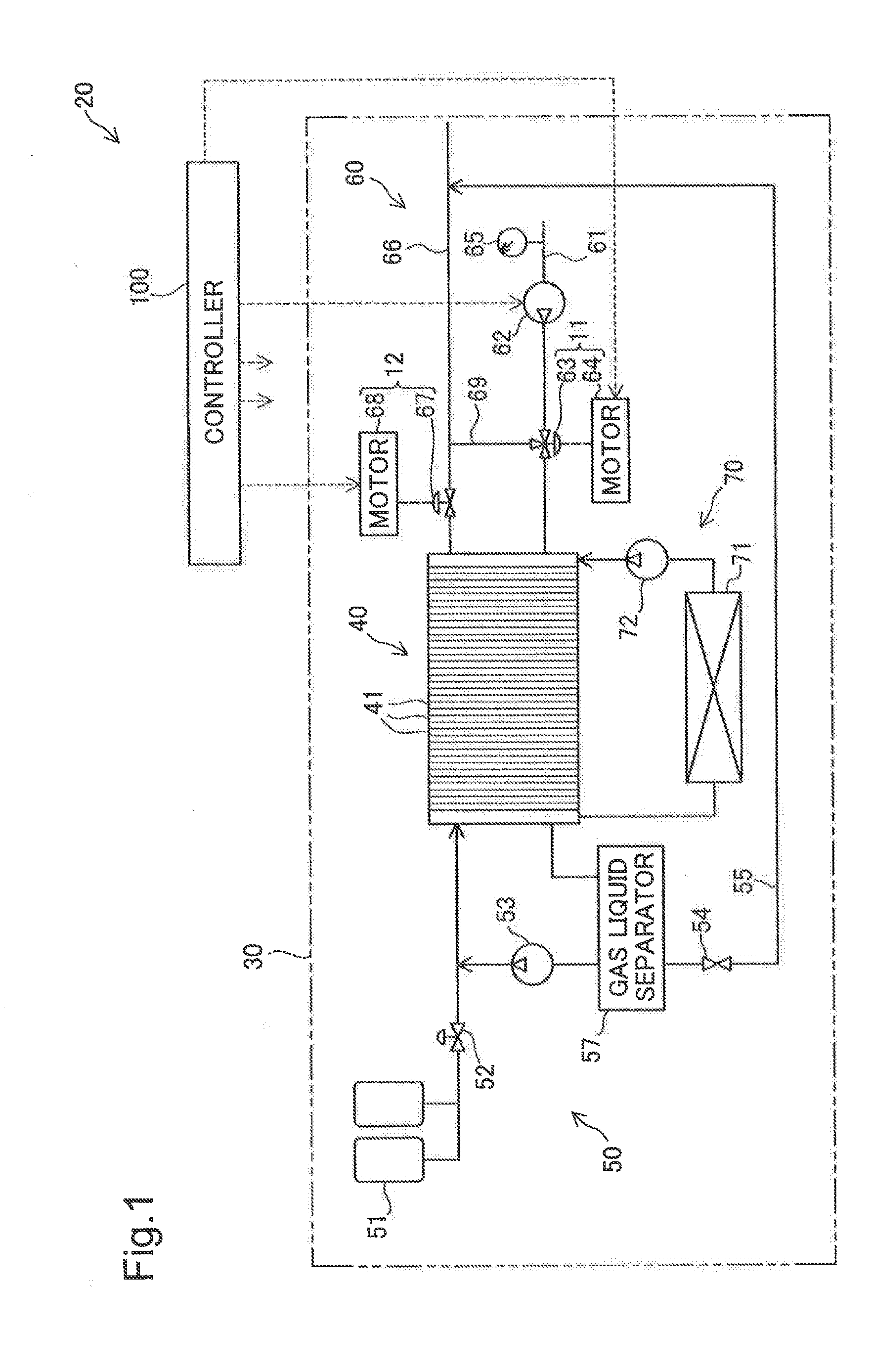
[0030]FIG. 1 is a block configuration diagram illustrating the schematic configuration of a fuel cell vehicle 20. The fuel cell vehicle 20 is a four-wheel vehicle and includes a fuel cell system 30 as shown in FIG. 1.

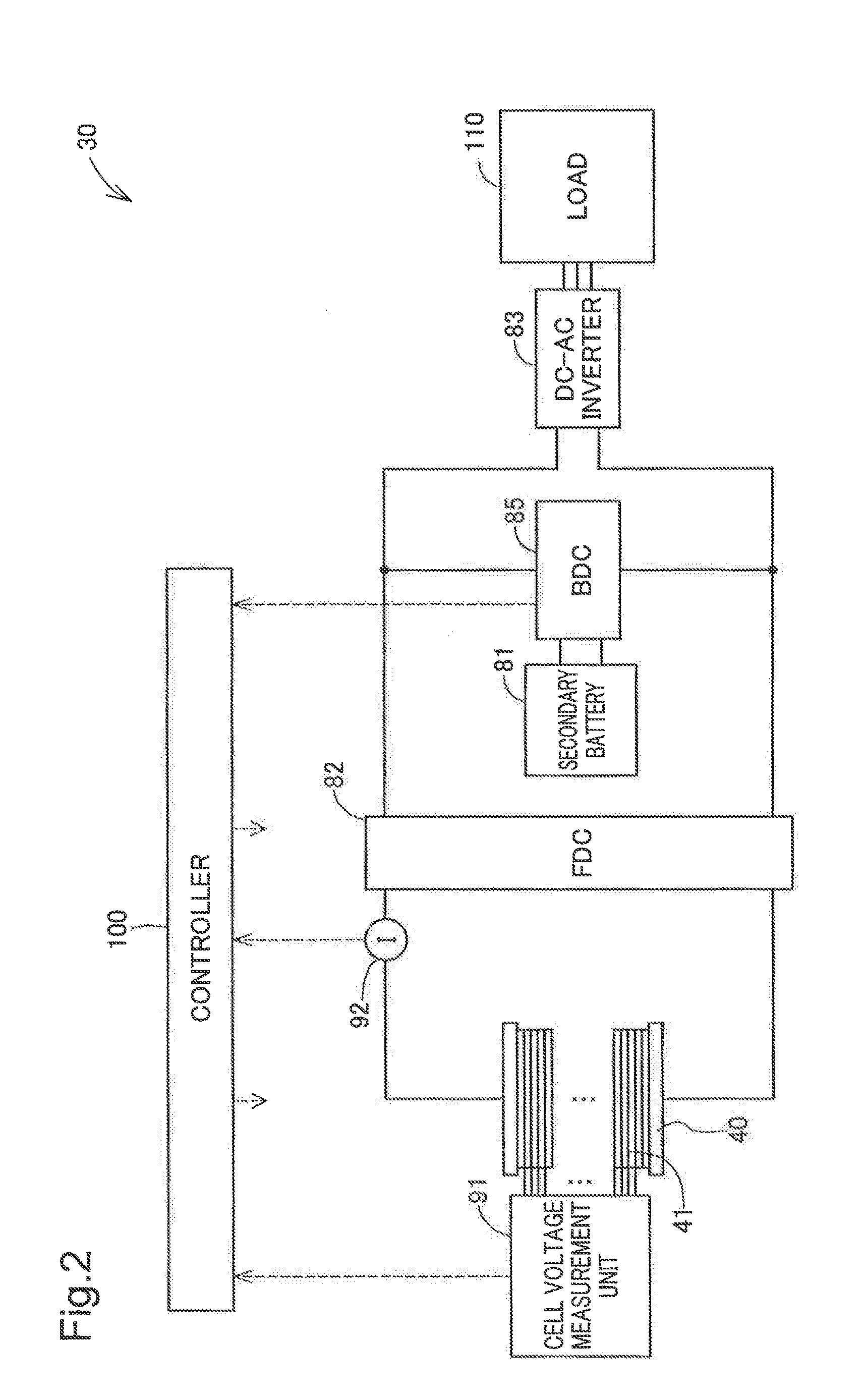
[0031]The fuel cell system 30 employs polymer electrolyte fuel cells to generate electric power by the reaction of hydrogen with oxygen. As shown in FIG. 1, the fuel cell system 30 includes a fuel cell stack 40, a hydrogen supply discharge mechanism 50, a cathode gas supply discharge mechanism 60, a cooling water circulation mechanism 70 and a controller 100.

[0032]The fuel cell stack 40 is provided by stacking a plurality of unit cells 41. Each unit cell 41 includes an anode, a cathode, an electrolyte membrane and separators. In the description hereof, the anodes of the plurality of unit cells 41 are collectively referred to as “anode”, and the cathodes of the plurality of unit cells 41 are collectively referred to as “cathode”.

[0033]The hydrogen supply discharge mechan...


PUM

PropertyMeasurementUnit
temperatureaaaaaaaaaa
poweraaaaaaaaaa
torqueaaaaaaaaaa

Abstract

A fuel cell system, comprising: a compressor that is placed in a supply flow path arranged to supply a cathode gas to a fuel cell; a first motor-operated valve that is placed between the fuel cell and the compressor in the supply flow path; a first stepping motor that is provided in the first motor-operated valve; a second motor-operated valve that is placed in a discharge flow path arranged to discharge the cathode gas from the fuel cell; a second stepping motor that is provided in the second motor-operated valve; and a controller that is configured to control power generation by the fuel cell and to input drive pulses into the first stepping motor and the second stepping motor, so as to open the first motor-operated valve and the second motor-operated valve at a start of the fuel cell and close the first motor-operated valve and the second motor-operated valve at a stop of the fuel cell, wherein the first stepping motor is driven by input of the drive pulse to generate a torque to open and close the first motor-operated valve, and the second stepping motor is driven by input of the drive pulse to generate a torque to open and close the second motor-operated valve, wherein the controller determines whether at least one of the first motor-operated valve and the second motor-operated valve is in a frozen state at the start of the fuel cell, when it is determined that neither the first motor-operated valve nor the second motor-operated valve is in the frozen state, the controller starts power generation by the fuel cell, and when it is determined that at least one of the first motor-operated valve and the second motor-operated valve is in the frozen state, the controller performs a predetermined process that repeats, a multiple number of times, alternately inputting a first drive pulse that generates a torque in a direction of increasing a valve opening and a second drive pulse that has a higher pulse speed than a pulse speed of the first drive pulse and generates a torque in a direction of decreasing the valve opening, to a stepping motor provided in at least the motor-operated valve in the frozen state out of the first stepping motor and the second stepping motor.

Description

CROSS-REFERENCE TO RELATED APPLICATIONS[0001]The present application claims priority from Japanese patent application P2015-128908 filed on Jun. 26, 2015, the content of which is hereby incorporated by reference into this application.BACKGROUND[0002]Field[0003]The present invention relates to a fuel cell system.[0004]Related Art[0005]Various valves are used in a fuel cell system. Any of these valves may be frozen in a closed state during a stop of the fuel cell system. It is difficult to open the valve in the frozen state. This is likely to interfere with starting the fuel cell system. JP 2005-285686A discloses a technique of repeating opening and closing operations of a solenoid valve to eliminate the frozen state of the valve.[0006]The target of this prior art technique is the solenoid valve that generates a relatively large force by the valve-opening and valve-closing operations. The valve-opening and valve-closing operations are thus expected to eliminate the frozen state to a c...

Claims


Application Information

Patent Timeline
Patent Type & Authority Applications(United States)
IPC IPC(8): H01M8/04223H01M8/04228H01M8/04111H01M16/00H01M10/44B60L11/18H01M8/04828H01M8/04955H01M8/04664H01M10/46H01M10/42H01M8/04225H01M8/04746
CPCH01M8/04253H01M2220/20H01M8/04228H01M8/04111H01M16/006H01M10/44H01M8/04753H01M8/04925H01M8/04955H01M8/04664H01M10/46H01M10/425B60L11/1881H01M2250/20H01M8/04225H01M8/04947H01M8/04089B60L58/30Y02T90/40Y02E60/50Y02E60/10H01M8/04302
Inventor YAMANAKA, TOMIOTOIDA, MASASHINAGANUMA, YOSHIAKINADA, MITSUHIRO
Owner TOYOTA JIDOSHA KK
Why Eureka
Try Eureka