Fastening device

a technology of fastening device and thread, which is applied in the direction of fastening means, screws, washers, etc., can solve the problems of major social problems, loose thread devices, and accidents resulting from loosening that have never been stopped, so as to prevent loose threads and inhibit force in a twisting direction

Inactive Publication Date: 2016-12-29
OKA KAZUTOMI
View PDF2 Cites 9 Cited by
  • Summary
  • Abstract
  • Description
  • Claims
  • Application Information

AI Technical Summary

Benefits of technology

[0012]As a result of these occurring at the same time, the thread surface slides against the friction force at the portion where the thread of the external thread portion 23 and the thread of the internal thread portion 13 of the nut 25 are engaged, and the engaged portion displaces in a loosening direction, resulting in loosening of the threads. In this case, even if the applied external force is not large enough to cause full sliding of each bearing surface of the head 22 of the hexagon head bolt 20 and the nut 25, which is defined as local sliding of the bearing surfaces with fastened portion being maintained at all times, sliding of the thread surface and displacement in the loosening direction are repeated in different directions due to the external force, allowing loosening of threads to progress little by little. Decrease in the fastening force and rapid loosening of the threads result eventually, causing full sliding of bearing surfaces.
[0014]The present inventor focused attention on those points and found that loosening of threads can be prevented by providing the seat of various threaded devices with a portion that slides earlier than the engaged portion, thereby inhibiting force in a twisting direction from being generated to the threaded parts.

Problems solved by technology

However, it is also known that threaded devices get loose while being used.
Accidents resulting from loosening have never ceased, and even emerge as major social problems depending on circumstances.
Loosening due to external force repetitively applied in a direction orthogonal to the axial direction is acknowledged as a major problem because the looseness cannot be assessed easily due to slow progress.

Method used


Image

  • Fastening device
  • Fastening device
  • Fastening device

Examples


first embodiment

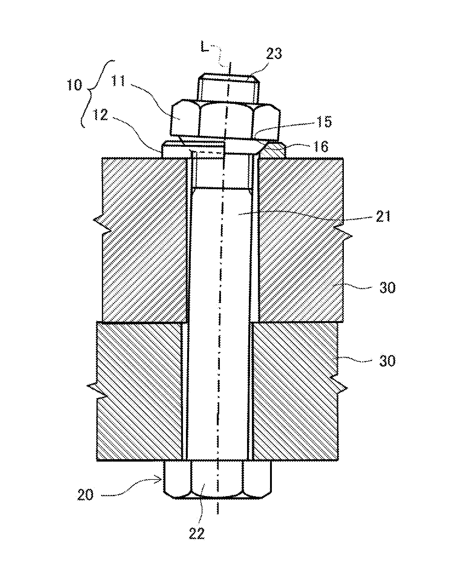
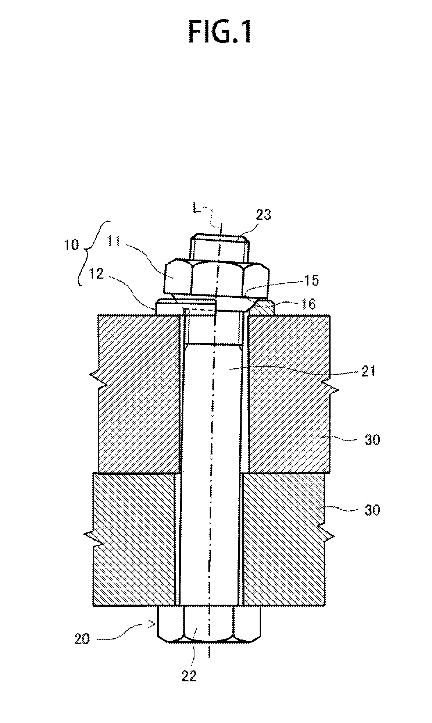
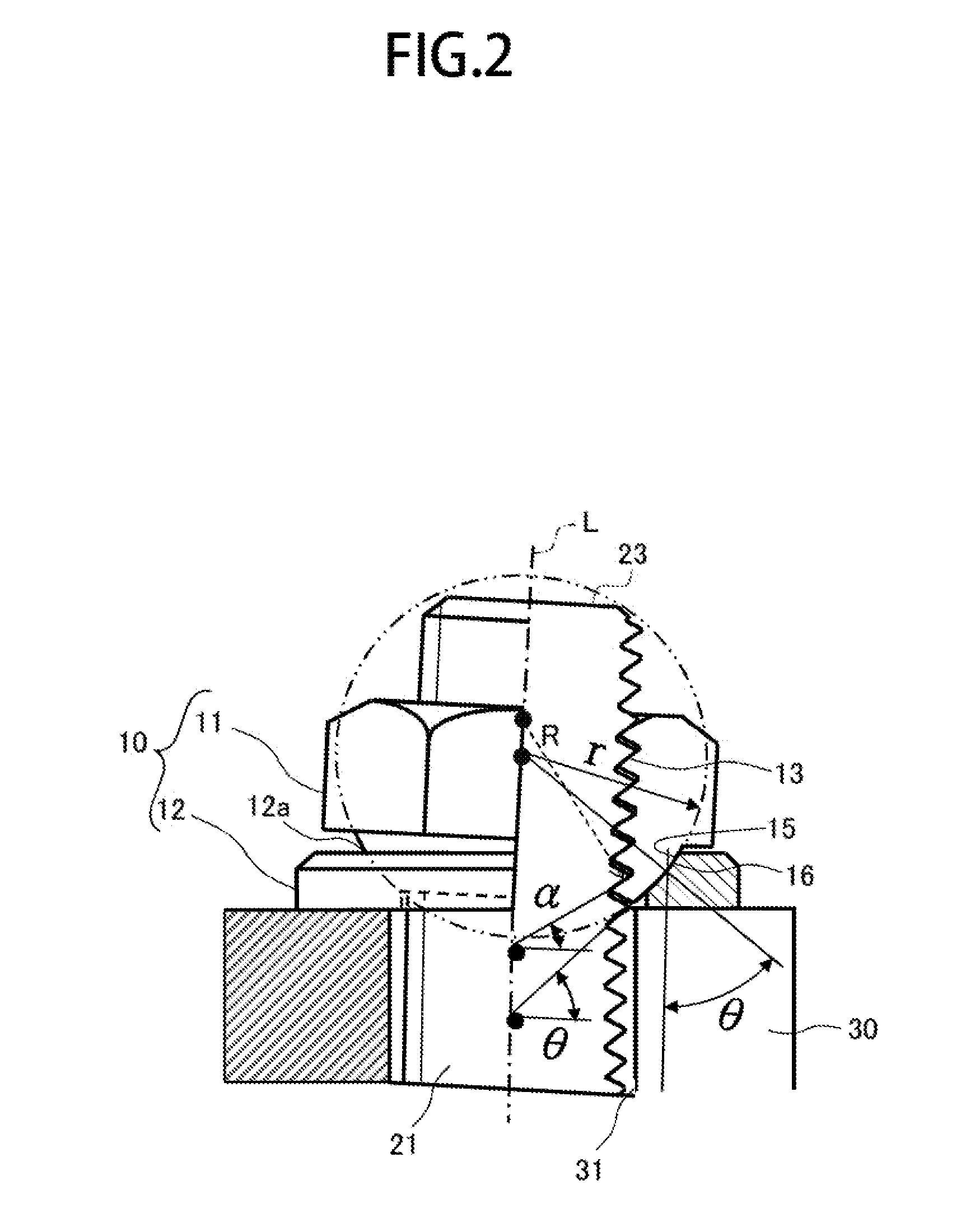
[0028]FIG. 1 is a cross-sectional view showing a state where a plurality of members to be fastened are fastened by using a fastening device according to first embodiment of the present invention. In a first embodiment, as shown in FIG. 1, internally threaded device 10 and a hexagon head bolt 20 are used to fasten a plurality of members to be fastened 30, 30. The shaft portion 21 of the hexagon head bolt 20 is disposed, penetrating into holes 31, 31 of the members to be fastened 30, 30. In a state where the bearing surface on a side of the head 22 abuts against, the surface of one member to be fastened 30, the external thread portion 23 protrudes from the other member to be fastened 30 on the end of the shaft portion 21. The internally threaded device 10 in a first embodiment is mounted to the external thread portion 23 of the hexagon head bolt 20. The external thread portion 23 is a triangular screw thread.

[0029]The internally threaded device 10 in the first embodiment includes a ma...

second embodiment

[0044]FIG. 4 is a cross-sectional view showing a state where members to be fastened are fastened by using externally threaded device according to a second embodiment of the present invention. In the second embodiment, as shown in FIG. 4 a plurality of members to be fastened 30, 30 are fastened by using externally threaded device 40. In this case, the externally threaded device 40 is disposed, penetrating into the hole 31 of one members to be fastened 30 and being engaged with an internal thread portion 13 provided on the other member to be fastened 30. The external thread portion 23 and the internal thread portion 13 are triangular screw threads.

[0045]The externally threaded device 40 includes a main external thread body 41 and a ring-like external thread seat portion 42. The main external thread body 41 has a shaft portion 21, which is provided with an external thread portion 23, and a head portion 22. The external thread seat portion 42 is disposed between the head portion 22 and ...

third embodiment

[0050]FIG. 5 is a cross-sectional view showing a state where members to be fastened are fastened by using a washer device according to a third embodiment of the present invention. In the third embodiment, as shown in FIG. 5, the washer device 50 is used together with a hexagon head bolt 20, which is externally threaded device, and a nut 25, which is internally threaded device, to fasten a plurality of members to be fastened 30, 30. In this case, the hexagon head bolt 20 is disposed, penetrating the plurality of members to be fastened 30, 30, and in a state where the seat of the head portion 22 abuts against the surface of one member to be fastened 30, the external thread portion 23 on the other end of the shaft portion 21 protrudes from the other member to be fastened 30 and is engaged with the nut 25. The washer device 50 is mounted between the nut 25 and the other member to be fastened 30.

[0051]The washer device 50 includes a first seat portion 51 and a second seat portion 52, Whi...


PUM


Abstract

Internally threaded device 10 includes a main body 11 having an internal thread portion 13 and a ring-like seat portion 12 disposed between the main body 11 and a member to be fastened 30. The main body 11 has a convex portion 15 and the ring-like seat portion 12 has a concave portion 16, the convex portion 15 and the concave portion 16 have a spherical zone with a center on an axis line. The radius of the spherical shape is set to allow the convex portion 15 and the concave portion 16 to slide earlier than the internal thread portion 13 when a load is applied between the main part 11 and the member 30 in a direction crossing the axial line L. Externally threaded device 40 and washer device 50 in similar structures prevent loosening of the engaged portion easily.

Description

[0001]This application claims the benefit of Japanese Application No.2015-126068 filed in Japan on 23 Jun. 2015, which is herein incorporated by reference in its entirety.BACKGROUND OF THE INVENTION[0002]Field of the invention[0003]This invention relates to a fastening device, such as internally threaded device, externally threaded device, and Washer device[0004]Description of the Related Art[0005]Threaded devices such as bolts, machine screws, and nuts have conventionally been used to fasten various members. Because of their moderate price and ease of attachment / detachment, threaded devices are widely used for structures and mechanical appliances. However, it is also known that threaded devices get loose while being used. Accidents resulting from loosening have never ceased, and even emerge as major social problems depending on circumstances.[0006]Causes of loosening include those not involving the rotation of engaged portion such as deformation and yield of internally and external...

Claims


Application Information

Patent Timeline
Patent Type & Authority Applications(United States)
IPC IPC(8): F16B39/24
CPCF16B39/24F16B39/28F16B5/0225F16B43/02
Inventor OKA, KAZUTOMI
Owner OKA KAZUTOMI
Why Eureka
Try Eureka