
Spacecraft and orbital plane change method therefor

a technology for spacecraft and orbital planes, applied in the field of orbital plane control of spacecraft, can solve the problems of long time period, and achieve the effects of short time period, reduced fuel consumption, and less fuel consumption

Active Publication Date: 2016-12-29
IHI AEROSPACE CO LTD
View PDF0 Cites 3 Cited by
  • Summary
  • Abstract
  • Description
  • Claims
  • Application Information

AI Technical Summary

Benefits of technology

The present invention provides a spacecraft and a method for changing the planetary position without using a lot of fuel. This is possible because the deceleration and acceleration required during re-entry and liftoff in the atmosphere have a significantly lower fuel consumption compared to traditional methods. Additionally, the change in position can be done quickly, within a few hours, by making a few circuits of the earth. Overall, the invention allows for a spacecraft to change its position quickly and efficiently with minimal fuel consumption.

Problems solved by technology

On the other hand, a drift caused by perturbation requires a long period of time (several ten days) to achieve the useful change in the orbit similarly.

Method used


Image

  • Spacecraft and orbital plane change method therefor
  • Spacecraft and orbital plane change method therefor
  • Spacecraft and orbital plane change method therefor

Examples


example

[0086]The following describes examples of trial calculation that compares the present invention to the conventional method.

[0087]FIG. 7 is a relationship diagram between the altitude from the earth and an atmospheric density therearound. In this figure, the vertical axis represents the altitude [km] and the horizontal axis represents the atmospheric density [kg / m3].

[0088]In this figure, the atmospheric density at altitudes of 600 to 800 km is approx. 1.0×10⁻¹³ kg / m3 and the atmospheric density at altitudes of 200 to 300 km is approx. 1.0×10⁻¹⁰ kg / m3, and it is understood that the atmospheric density of the latter is about 1,000 times higher than the former.

[0089]Similarly, the atmospheric density at altitudes of 50 to 100 km is approx. 1.0×10⁻³ to 1.0×10⁻⁶ kg / m3, and it is understood that the atmospheric density at the altitudes is about 104 to 107 times higher than that at altitudes of 200 to 300 km.

[0090]Since atmospheric drag (air resistance) is proportional to atmospheric densit...


PUM


Abstract

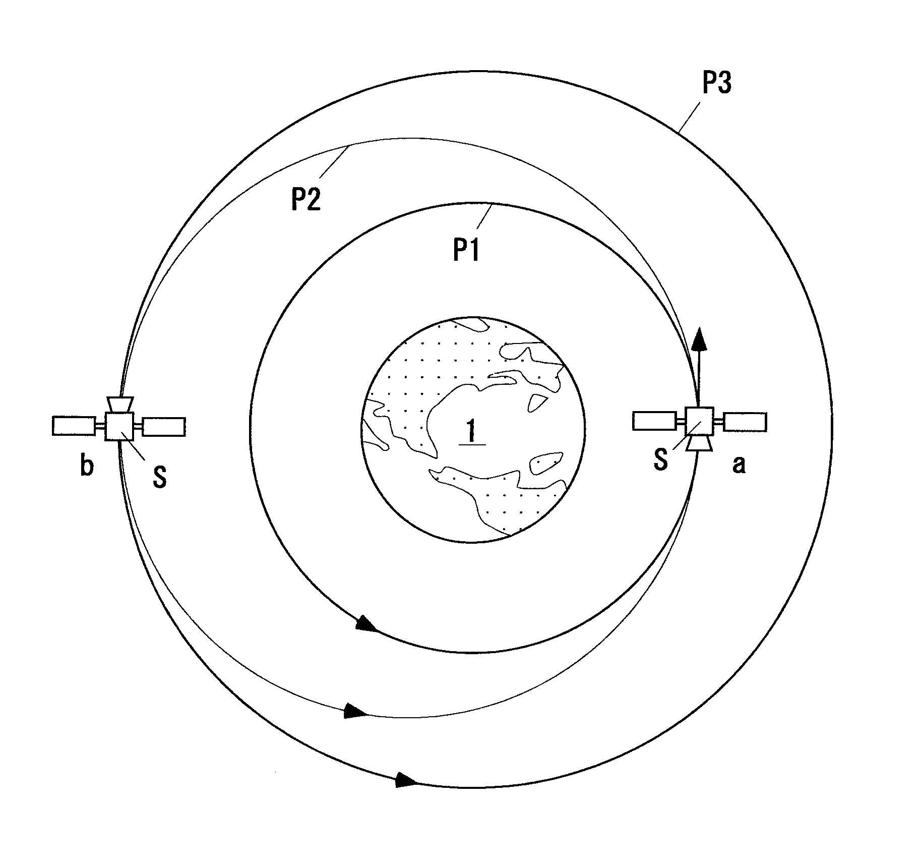
A spacecraft 10 includes wings 11 or an airframe 12 which generates lift in an atmosphere 2, a thruster 14 which accelerates or decelerates rotating speed in an orbit, an attitude controller 16 which controls an attitude of the airframe 12, and an orbital plane controller 18 which controls the orbital plane change. The orbital plane controller causes the spacecraft 10 to enter the earth's atmosphere 2 within a pre-change orbital plane Fb (A→B→C), changes the orbital plane by using the lift of the wings 11 or airframe 12 in the earth's atmosphere 2 (C→D→E), and then lifts the spacecraft 10 up to the post-change orbital altitude (E→F).

Description

BACKGROUND OF THE INVENTION[0001]Field of the Invention[0002]The present invention relates to an orbital plane control of a spacecraft and more specifically to a spacecraft and an orbital plane change method therefor for changing the orbital plane of a rotating orbit around the earth to another orbital plane different in the orbital inclination or in the right ascension of the ascending node.[0003]Background Art[0004]Changing the orbit of a satellite is referred to as “orbit control (correction).” An orbit control method is able to be mainly classified into in-plane control and orbital plane control.[0005]The term “in-plane control” means changing the size and shape of the orbit by firing engines for acceleration or deceleration within the orbital plane of the satellite.[0006]The term “orbital plane control” means changing an angle of the orbital plane to the equator (the angle is referred to as “orbital inclination”) or an angle formed by a point at which the orbit intersects the e...

Claims


Application Information

Patent Timeline
IPC IPC(8): B64G1/24B64G1/26
CPCB64G1/26B64G1/242B64G1/14B64G1/62B64G1/2427
Inventor FUJIMURA, MASANOBUSUGIMURA, FUMITAKAAMIMOTO, JUNICHITAKADA, TETSUYAMORISAKI, HIROTAKE
Owner IHI AEROSPACE CO LTD
Learn More