Aircraft structural component that is adapted for absorbing and transmitting forces in an aircraft

a technology for aircraft and structural components, applied in the direction of mechanical equipment, transportation and packaging, fastening means, etc., can solve the problems of reducing the service life of the machined bracket, so as to improve the distribution of absorbed forces and reduce the weight. , the effect of high resistan

Active Publication Date: 2016-12-29
AIRBUS HELICOPTERS DEUT GMBH
View PDF7 Cites 7 Cited by
  • Summary
  • Abstract
  • Description
  • Claims
  • Application Information

AI Technical Summary

Benefits of technology

[0014]It is, therefore, an object of the present invention to provide an aircraft structural component that is adapted for absorbing and transmitting forces in an aircraft and, in particular, in a rotary wing aircraft, said aircraft structural component being inherently protected against corrosion and exhibiting a comparatively low weight and a high resistance against forces that are to be absorbed and transferred, while providing for an improved distribution of absorbed forces.

Problems solved by technology

Usually, such a machined bracket consists of an aluminum alloy such that corrosion thereof can at least be limited.
However, such a machined bracket is comparatively costly and heavy.
Furthermore, mounting of the machined bracket to the rotary wing aircraft is a complicated and laborious task, which is time-consuming and expensive.
Moreover, for riveting the machined bracket to the FRP fuselage, the latter must be provided with corresponding rivet-receiving openings, which are potential failure sources.
In addition, such a machined bracket must efficiently be protected against corrosion by suitable measures, as even aluminum brackets may be affected by long-term corrosion.
Finally, metal parts in general and, thus, also the machined aluminum bracket and corresponding screws and / or rivets that are used for attaching the latter to the FRP fuselage are as such prone to fatigue.
However, this connecting element in the form of an additional hook and loop layer defines a detachable connection and is not designed to transfer comparatively high shear loads that occur e.g. in a wheel-type nose landing gear of a rotary wing aircraft as described above.
Furthermore, due to application of such an additional hook and loop layer to the aircraft structural component, the latter becomes comparatively heavy.
Moreover, this additional hook and loop layer is complicated and time-consuming in manufacture and, thus, expensive.

Method used


Image

  • Aircraft structural component that is adapted for absorbing and transmitting forces in an aircraft
  • Aircraft structural component that is adapted for absorbing and transmitting forces in an aircraft
  • Aircraft structural component that is adapted for absorbing and transmitting forces in an aircraft

Examples


Embodiment Construction

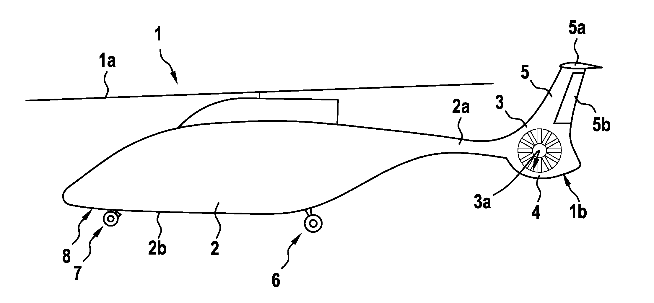
[0058]FIG. 1 shows a vehicle 1 that is exemplarily illustrated as an aircraft, in particular as a rotary wing aircraft and, more particularly, as a helicopter. Thus, for purposes of simplicity and clarity, the vehicle 1 is hereinafter referred to as the “helicopter 1”. The present invention is, however, not limited to helicopters and can likewise be applied to any other vehicle, for instance a vehicle that is controllable in a flowing medium, such as air or water, independent of a particular configuration thereof. Therefore, the helicopter 1 is only briefly described by way of example for illustrating a possible field of application of the present invention, but not for restricting the present invention thereto.

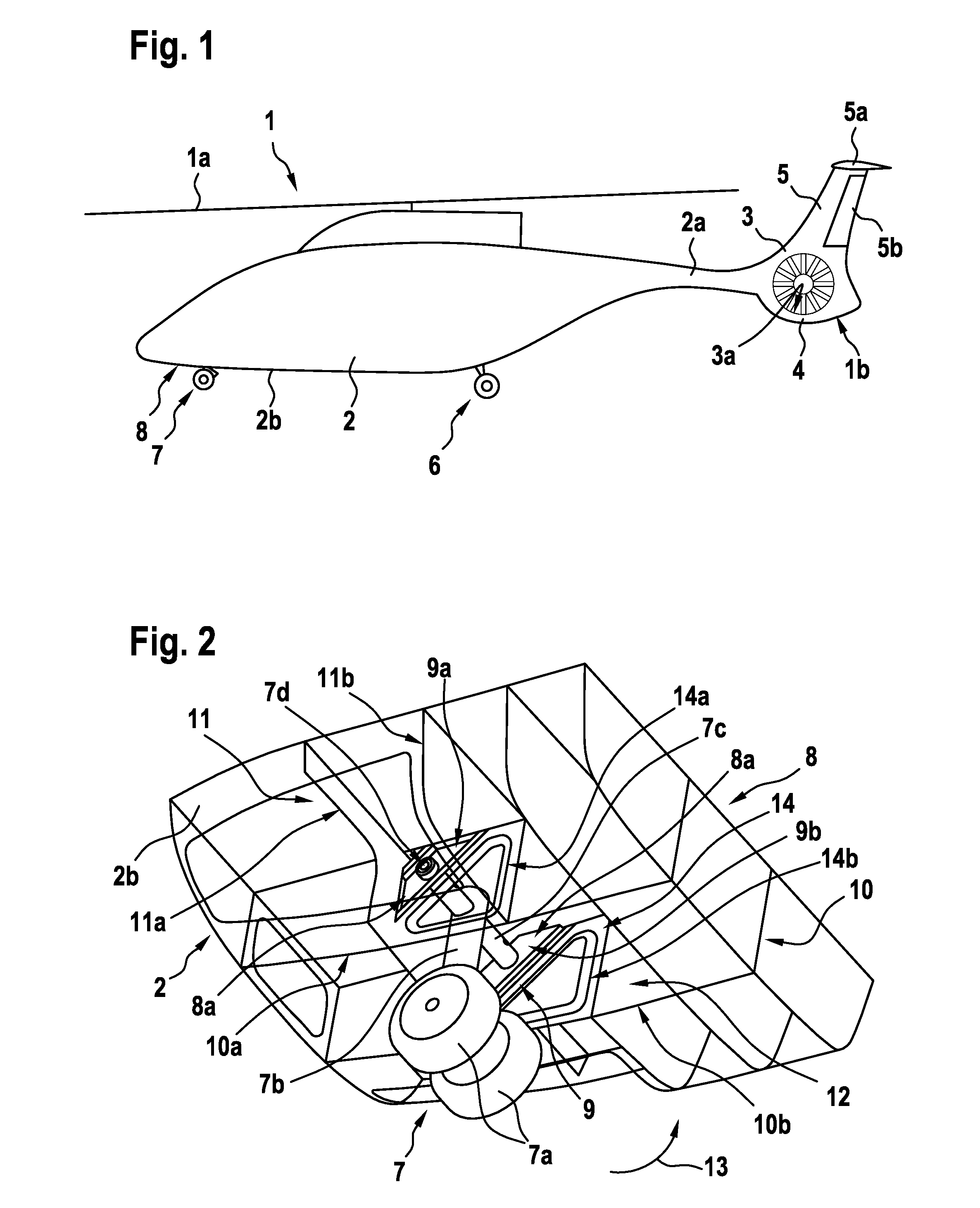
[0059]The helicopter 1 illustratively comprises a fuselage 2 that defines a tail boom 2a. According to one aspect of the present invention, the fuselage 2 comprises a bottom shell 2b that is equipped with a force-absorbing structure 8. Preferably, the force-absorbing structur...


PUM


Abstract

An aircraft structural component that is adapted for absorbing and transmitting forces in an aircraft, the aircraft structural component comprising at least one panel element and at least one reinforcing structure. The at least one reinforcing structure is rigidly attached to the at least one panel element such that at least one cavity is defined between the at least one panel element and the at least one reinforcing structure, the at least one cavity being adapted for distributing forces that are absorbed by the aircraft structural component in operation.

Description

CROSS REFERENCE TO RELATED APPLICATION[0001]This application claims priority to European patent application No. EP 15400026.9 filed on Jun. 29, 2015, the disclosure of which is incorporated in its entirety by reference herein.BACKGROUND OF THE INVENTION[0002](1) Field of the Invention[0003]The invention is related to an aircraft structural component that is adapted for absorbing and transmitting forces in an aircraft.[0004]In general, aircraft structural components are used in aircrafts to strengthen locations where comparatively high loads must be transferred between different aircraft elements or structures. By way of example, such comparatively high loads occur with respect to a wheel-type landing gear of an aircraft and, more particularly, during landing of the aircraft, when comparatively high landing loads are induced via corresponding landing gear wheels of the wheel-type landing gear into the aircraft's fuselage. For instance, if the aircraft is embodied as a rotary wing air...

Claims


Application Information

Patent Timeline
Patent Type & Authority Applications(United States)
IPC IPC(8): B64C1/06B64C25/20B64C25/34B64C25/10B64C27/00
CPCB64C1/069B64C25/10B64C1/064B64C27/00B64C27/04B64C25/20B64C2025/325B64C2001/0054B64C25/34B64C1/00F16B5/01F16B9/00F16B11/006F16B9/056
Inventor VON-WILMOWSKY, KASPARREICHENSPERGER, CHRISTIANRACK, ANDREAS
Owner AIRBUS HELICOPTERS DEUT GMBH
Why Eureka
Try Eureka