
Switchable supply and tunable load impedance power amplifier

a power amplifier and switchable technology, applied in the field of wireless communication systems, can solve the problems of difficult to ensure reliability of bluetooth power amplifiers when wi-fi power amplifiers, difficult to configure output loads, etc., and achieve the effect of preventing damage to bluetooth power amplifiers and maximizing power efficiency of both bluetooth power amplifiers

Active Publication Date: 2016-12-22
QUALCOMM INC
View PDF2 Cites 15 Cited by
  • Summary
  • Abstract
  • Description
  • Claims
  • Application Information

AI Technical Summary

Benefits of technology

This patent describes a way to make Bluetooth and Wi-Fi power amplifiers more efficient by sharing an antenna. The patent introduces a circuit that includes a tunable load that can adjust the load impedance for each amplifier based on the operating mode of the circuit. Additionally, the circuit includes a switchable power supply that can adjust the supply voltage for Bluetooth based on its power needs. This circuit prevents damage to the Bluetooth amplifier while transmitting Wi-Fi signals from the antenna. The technical effects of this invention are improved power efficiency and better reliability of wireless circuits in mobile devices.

Problems solved by technology

For wireless devices including a Wi-Fi power amplifier and a Bluetooth power amplifier that share the same output load, it may be difficult to configure the output load in a manner that optimizes power transmission efficiency for both the Wi-Fi power amplifier and the Bluetooth power amplifier.
Further, for wireless devices in which an antenna is shared between the Wi-Fi power amplifier and the Bluetooth power amplifier, it may be difficult to ensure reliability of the Bluetooth power amplifier when the Wi-Fi power amplifier is transmitting (e.g., because the Wi-Fi power amplifier typically drives Wi-Fi signals at higher power levels than the power levels to which the Bluetooth power amplifier drives Bluetooth signals).

Method used


Image

  • Switchable supply and tunable load impedance power amplifier
  • Switchable supply and tunable load impedance power amplifier
  • Switchable supply and tunable load impedance power amplifier

Examples


Embodiment Construction

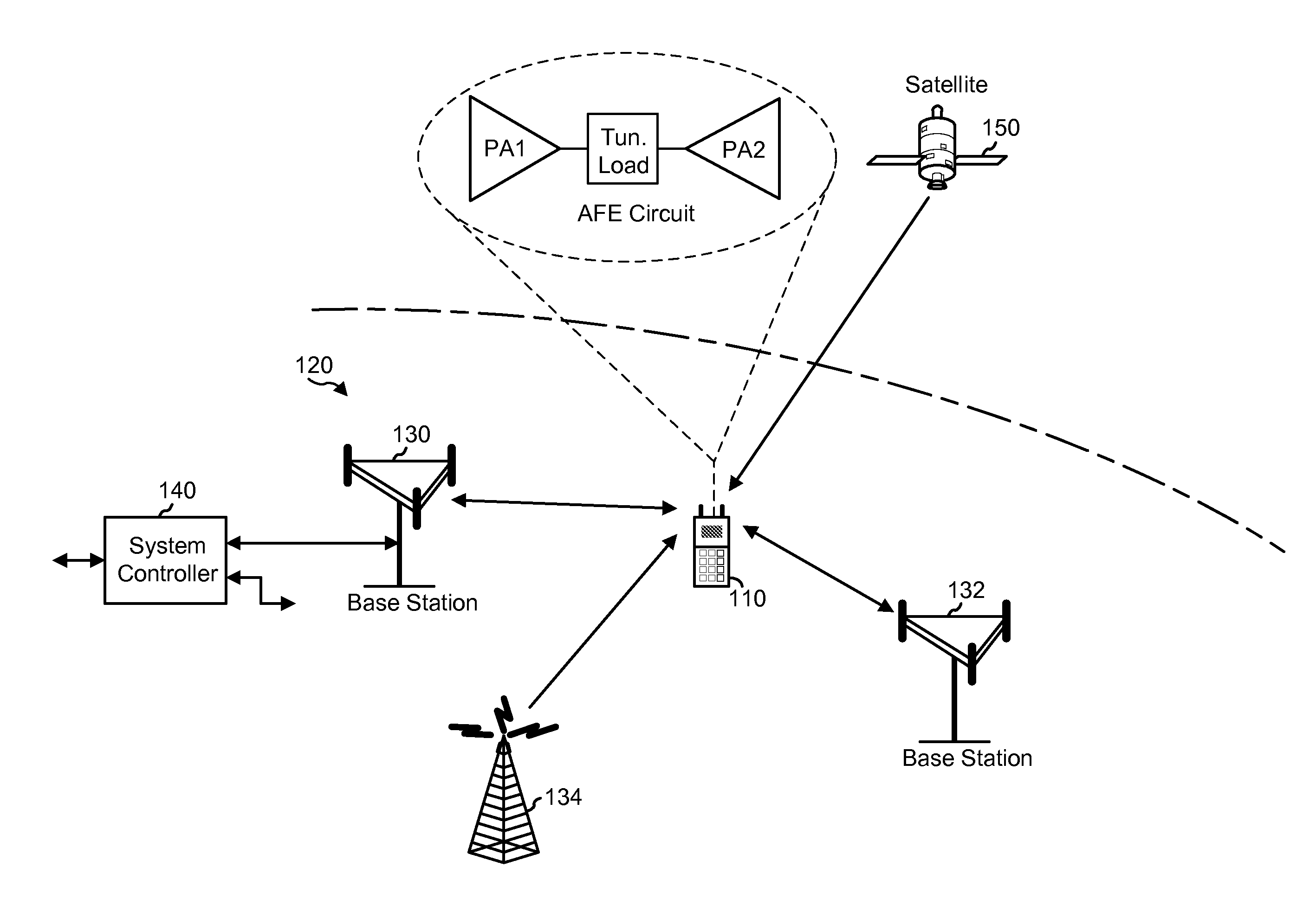
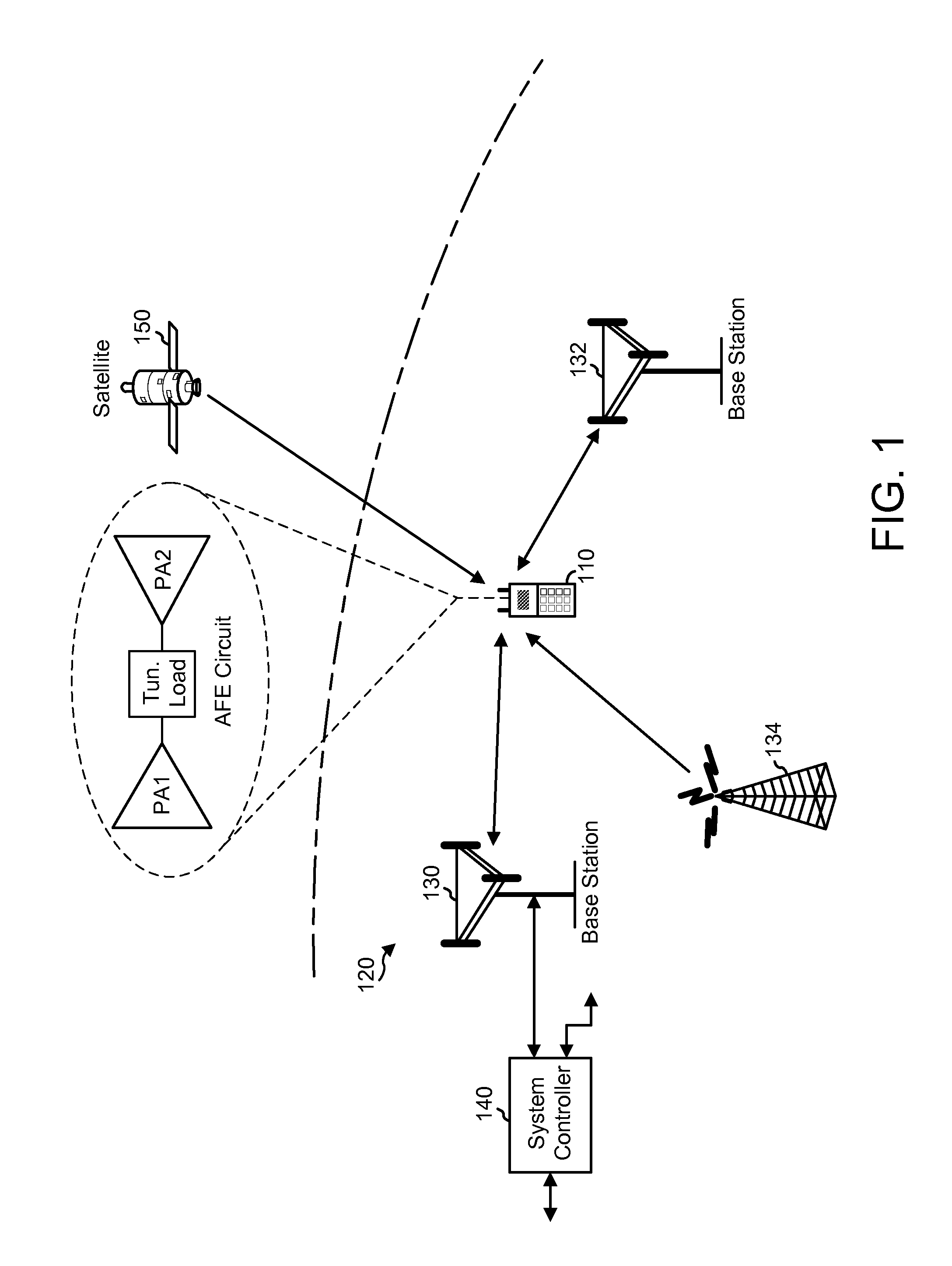
[0029]The example embodiments are described below in the context of WLAN and Bluetooth communications and networks for simplicity only. It is to be understood that the example embodiments are equally applicable to other types of communications and networks (e.g., cellular networks, pico networks, femto networks, satellite networks, etc.), as well as systems using signals of one or more wired standards or protocols (e.g., Ethernet and / or HomePlug / PLC standards). As used herein, the terms “WLAN” and “Wi-Fi®” may include communications governed by the IEEE 802.11 family of standards, HiperLAN (a set of wireless standards, comparable to the IEEE 802.11 standards, used primarily in Europe), and other technologies having relatively short radio propagation range. Further, as used herein, the term BLUETOOTH® (Bluetooth) may include communications governed by the Bluetooth Special Interest Group.

[0030]In the following description, numerous specific details are set forth such as examples of s...


PUM


Abstract

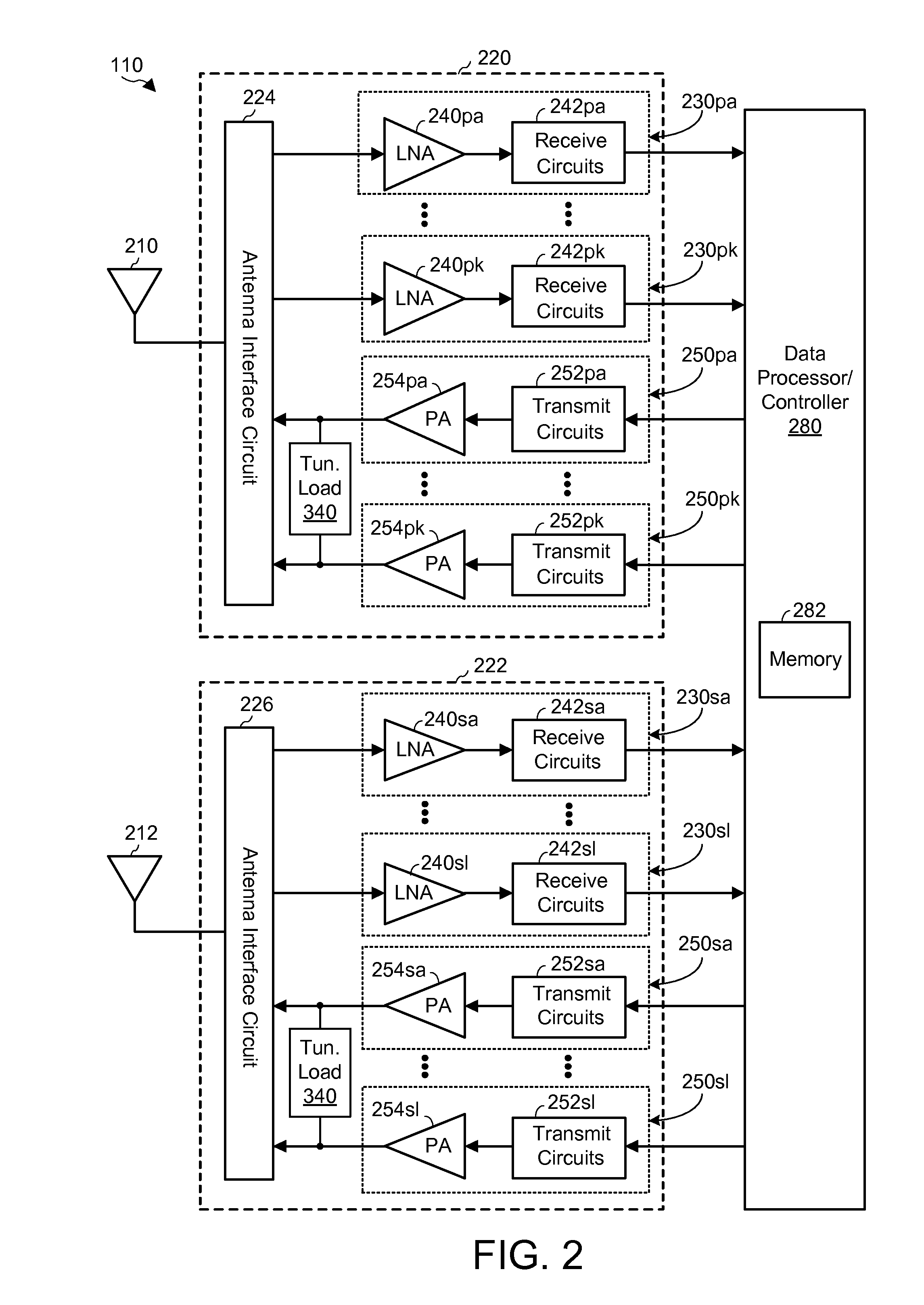
A transceiver configured to transmit data in a plurality of operating modes including a Wi-Fi mode and two or more different Bluetooth power modes, the transceiver comprising: a first power amplifier configured to amplify Bluetooth signals; a second power amplifier configured to amplify Wi-Fi signals; an antenna coupled to the second power amplifier; and a tunable load circuit, coupled between the first amplifier and the second amplifier, configured to provide a different load impedance for each of the plurality of operating modes, the tunable load circuit consisting of: two impedance paths coupled in parallel between output terminals of the first and second amplifiers; and a number of shunt paths coupled between the tunable load circuit and ground potential.

Description

TECHNICAL FIELD[0001]The present embodiments relate generally to wireless communications systems, and specifically to tunable load impedances for shared-antenna wireless communications systems.BACKGROUND OF RELATED ART[0002]Modern wireless communications devices typically include multiple wireless radios (e.g., Bluetooth®, Wi-Fi, etc.). To achieve a smaller footprint, multiple wireless radios may share the same antenna. For example, a wireless device may include a Bluetooth radio and a Wi-Fi radio coupled to a single antenna. The Bluetooth radio may include a Bluetooth power amplifier to drive (e.g., amplify) outgoing data signals in accordance with one or more Bluetooth standards. The Wi-Fi radio may include a Wi-Fi power amplifier to drive outgoing data signals in accordance with one or more IEEE 802.11 standards. The Bluetooth and Wi-Fi radios typically operate on the 2.4 GHz frequency band, and may share an antenna to transmit signals to other wireless devices and / or to receive ...

Claims


Application Information

Patent Timeline
Patent Type & Authority Applications(United States)
IPC IPC(8): H03F1/02H03F3/19H03F3/21H04W4/00H04W52/38H04W4/80
CPCH03F1/0205H04W4/008H04W52/38H03F3/211H03F2203/21106H04W84/12H04W88/06H03F2200/294H03F2200/451H03F3/19H04B1/0458H04W4/80
Inventor LIN, SAIHUACHOI, JONGHOON
Owner QUALCOMM INC
Learn More