
Secondary Battery Housing with Control Electronics

a second battery and control electronics technology, applied in secondary cells, battery servicing/maintenance, instruments, etc., can solve the problems of consuming more than 120 mw of all commercially available converters, insufficient protection of cells, and large amount of emi, and achieve the effect of low nois

Active Publication Date: 2016-12-22
BREN TRONICS INC
View PDF9 Cites 18 Cited by
  • Summary
  • Abstract
  • Description
  • Claims
  • Application Information

AI Technical Summary

Benefits of technology

The patent aims to create a device that can balance cells efficiently and effectively while reducing noise. The goal is to improve the overall performance and efficiency of the device.

Problems solved by technology

The packing configuration can occupy a large volume, inadequately protect the cells from impact shock or lead to overheating.
The prior art patent does not isolate battery packs from each other nor does it provide control electronics within the housing.
Most cell balance converters are either passive or utilize “hard switching topology.” The passive devices dissipate power leading to inefficiency.
The converters based on “hard switching topology” produce a large amount of EMI.
Furthermore, all commercially available converters suffer from consuming more than 120 mW, design limitations preventing operation at 33V, or no isolation.
The converter circuit has a complex secondary winding configuration and does not provide a capacitor in the series loop with the battery and the winding.
However, both references use multiple switches on each battery loop which adds to the cost, power usage and complexity of the control circuit.
Since these circuits draw from mains power, conserving space and low power consumption are not addressed.
U.S. Pat. No. 9,054,400 has the semiconductor switch attached to the bus, but does not disclose bidirectional switches with individual paths.
Current 6T batteries are non-smart batteries, having limitations with regard to interconnecting of batteries and display of State of Charge, Voltage, Current and other pertinent battery information.

Method used


Image

  • Secondary Battery Housing with Control Electronics
  • Secondary Battery Housing with Control Electronics
  • Secondary Battery Housing with Control Electronics

Examples


Embodiment Construction

[0049]The invention relates to the assembly of cell packs into a housing with integrated control electronics to form a rechargeable battery. The battery, for example, a Lithium-Ion (Li-Ion) Battery, may be useful for vehicle and other high capacity applications.

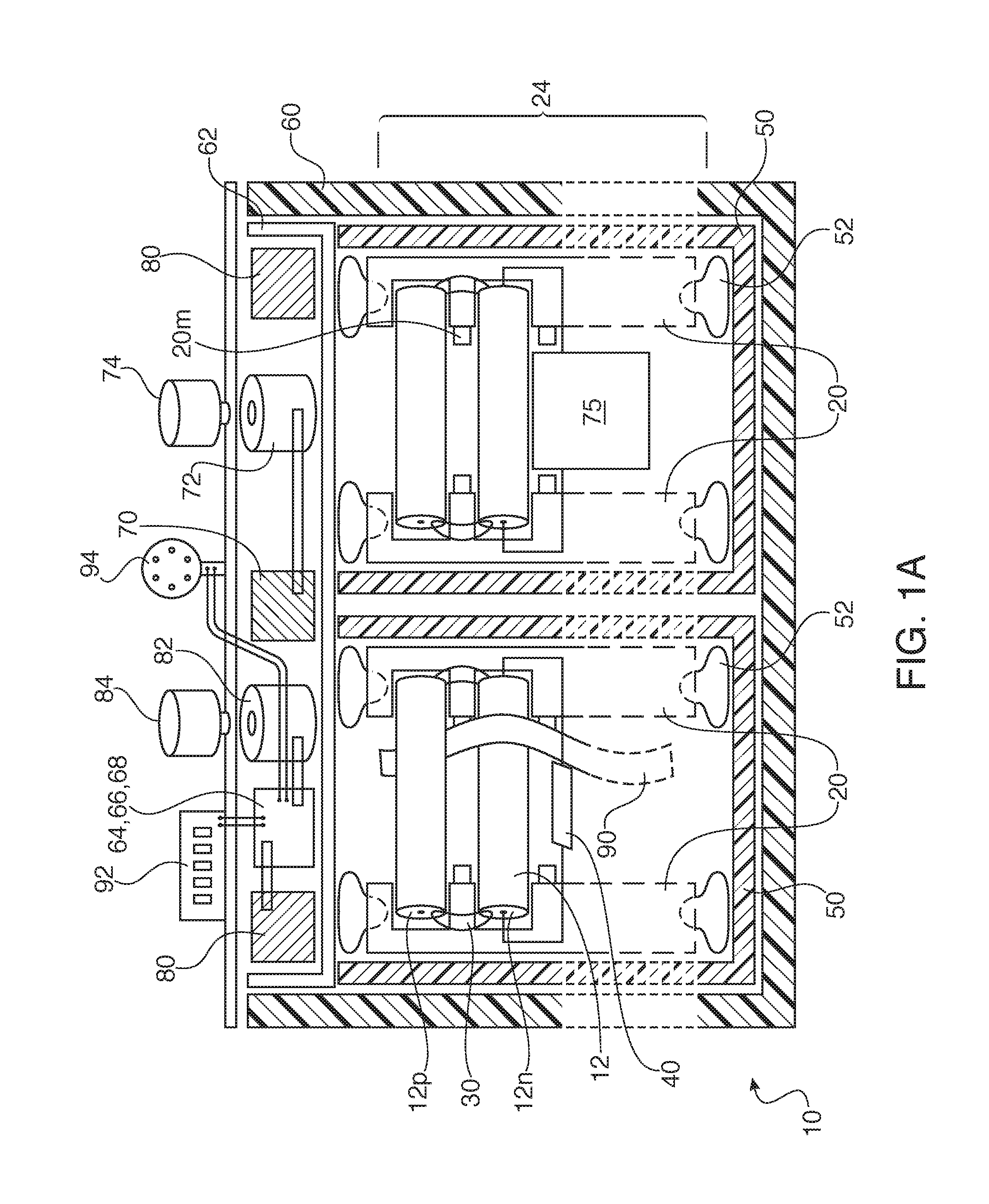
[0050]The arrangement of cells is critical to facilitate the assembly process. The series and parallel arrangements of cells are often inefficient to connect in an economical and functional arrangement. The assembly is shown in FIG. 1A as an apparatus 10 for electronically controlling and mechanically coupling cells together within a battery housing 60.

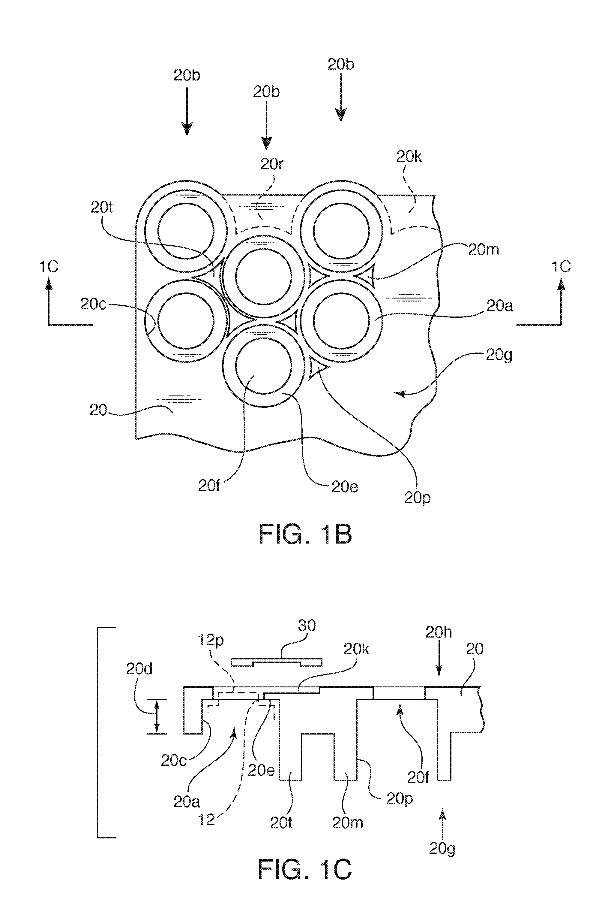
[0051]The 18650 cells are arranged into six cell packs. Two cell packs 24 are shown, in a first row, where two additional rows may by added behind the two cell packs shown. The cell packs are then tied in parallel with substantial bus bars. The construction of the cell packs uses two symmetrical honeycomb shaped parts to hold each end of the cylindrical cells (49 cells for 24v ...


PUM


Abstract

Rechargeable cells in cylindrical form are arranged within frames in a honeycomb structure and coupled by connecting straps outside the frames to form cell pack. Several cell packs, an electronic switch and control circuit are integrated into the battery housing. A bus bar extends around the perimeter of the housing. A high density MOSFET switch is coupled between the bur bar and the battery contact. A high power electronic clamp disposed across the battery terminals absorbs or redirects transients. An active, high-efficiency, low-noise cell balance converter or a LC based resonant converter may also be provided. For advanced battery applications a +5V CAN bus interface is provided via two circular connectors. Thermistors are provided for use in a thermal protection scheme.

Description

CROSS-REFERENCE TO RELATED APPLICATIONS[0001]This application claims the benefit under 35 U.S.C. §119(e) from U.S. Provisional Patent Application No. 62 / 167,499 entitled Rechargeable Batteries with Battery Management, High Current Switching and Protection, and Smart Battery Features filed May 28, 2015.BACKGROUND OF THE INVENTION[0002]1. Field of the Invention[0003]The invention relates to a secondary battery housing and control electronics.[0004]2. The Prior Art[0005]High capacity secondary batteries are formed by packing multiple rechargeable cells into a housing. The packing configuration can occupy a large volume, inadequately protect the cells from impact shock or lead to overheating. In addition, the battery requires sophisticated electronics to balance the charge between high and low voltage cells, protect the system from over-voltage conditions, efficiently convert power for output, provide suitable smart connectors, and provide battery status indicators.[0006]A prior art exa...

Claims


Application Information

Patent Timeline
IPC IPC(8): H01M10/42H02M3/335H02H7/18H01M10/0525H01M2/24H01M10/633H01M10/643H02J7/00H01M2/10H01M50/213H01M50/242H01M50/264H01M50/271H01M50/291H01M50/296H01M50/503H01M50/516H01M50/522H01M50/529
CPCH01M10/4264H02J7/0021H02J7/0019H02M3/33523H02H7/18H01M2010/4271H01M2/24H01M10/4207H01M10/633H01M10/643H01M10/0525H01M2/105H01M10/486H01M2200/103H02J7/0042Y02B70/10Y02E60/10H01M50/213H02J7/0048H02J7/007194H02J7/0014H01M50/522H01M50/516H01M50/264H01M50/291H01M50/296H01M50/242H01M50/503H01M50/271G01R31/36Y02B40/00Y02E60/13
Inventor CLEMENTE, TULLIOSQUILLANTE, ALANILKHANOV, AZERKAHN, JARREDSANDLER, DAVIDPACZKOWSKI, HENRYBURKE, PETER J.FUNG, SAI
Owner BREN TRONICS INC
Learn More