
Washpipe assembly

a technology of assembly and washpipe, which is applied in the direction of drilling pipes, drilling casings, borehole/well accessories, etc., can solve the problems of limited life of approximately 200 hours or less, damage to the floating function of the floating seal assembly, and difficulty in replacing the sealing arrangement, so as to achieve convenient installation and commissioning, reliable sealing, and easy to work.

Active Publication Date: 2016-12-22
BEIJING JJC PETROLEUM EQUIP
View PDF7 Cites 1 Cited by
  • Summary
  • Abstract
  • Description
  • Claims
  • Application Information

AI Technical Summary

Benefits of technology

The present invention is a washpipe assembly that has an improved sealing ability between the stationary seal ring and the rotating seal ring, making it easier and faster to install and commission. The ceramic rings on the stationary and rotating seal rings are designed with O-ring chambers to facilitate easy maintenance. The washpipe assembly is reliable, durable, and can handle high pressures, making it ideal for use in drilling and wellbore operations. The configuration of the washpipe and the differential pressure between the various parts of the assembly provide excellent sealing performance and safety during drilling operations.

Problems solved by technology

The traditional type have a limited lifetime of approximately 200 hours or less in average, and have difficulty to replace the sealing arrangement because the device is installed at a high location, in a limited space, and configured with heavy hammer unions.
The force between the floating seal member and the anti-rotating rods damages the floating function of the floating seal assembly.
The fixed installation of the washpipe member with respect to the stationary structure and the limited cylindrical clearance between the floating seal member and the washpipe member also limits the following capacity of the stationary seal ring to the rotating seal ring.
The limited floating and / or following capacity of the above mentioned washpipe assembly asks a demanding installation interface, which results in a difficult installation and commissioning work.
Because the O-ring grooves are directly exposed to the drilling fluid during the operations, and the space for replacing the seal rings is very limited, it takes time to clean the grooves when replacing seal rings, which results in an extended downtime of the drilling operations.

Method used


Image

  • Washpipe assembly
  • Washpipe assembly
  • Washpipe assembly

Examples


Embodiment Construction

[0027]Exemplary embodiments of the present disclosure will be described hereinafter in detail with reference to the attached drawings, wherein the like reference numerals refer to the like elements. The present disclosure may, however, be embodied in many different forms and should not be construed as being limited to the embodiment set forth herein; rather, these embodiments are provided so that the present disclosure will be thorough and complete, and will fully convey the concept of the disclosure to those skilled in the art.

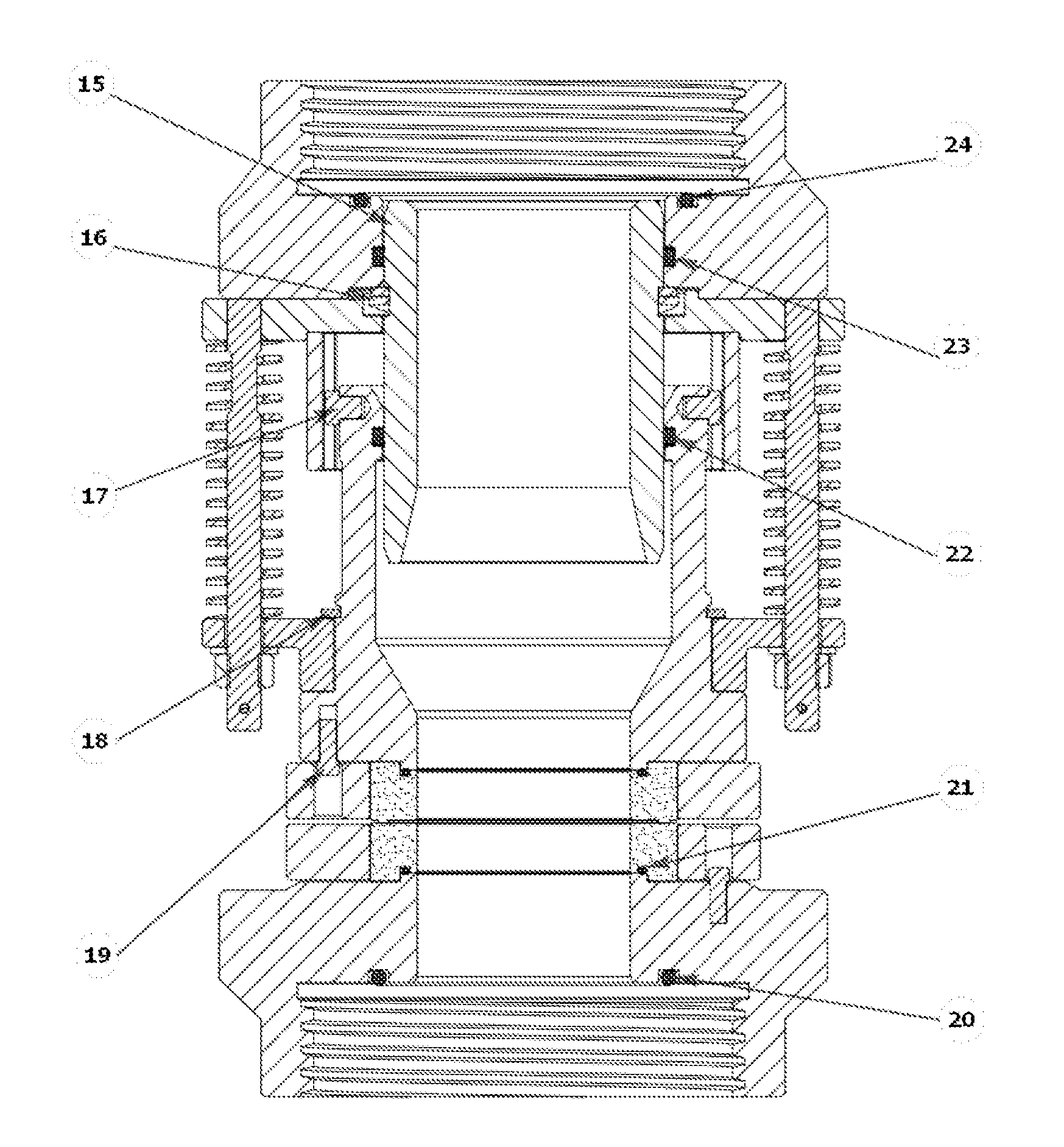
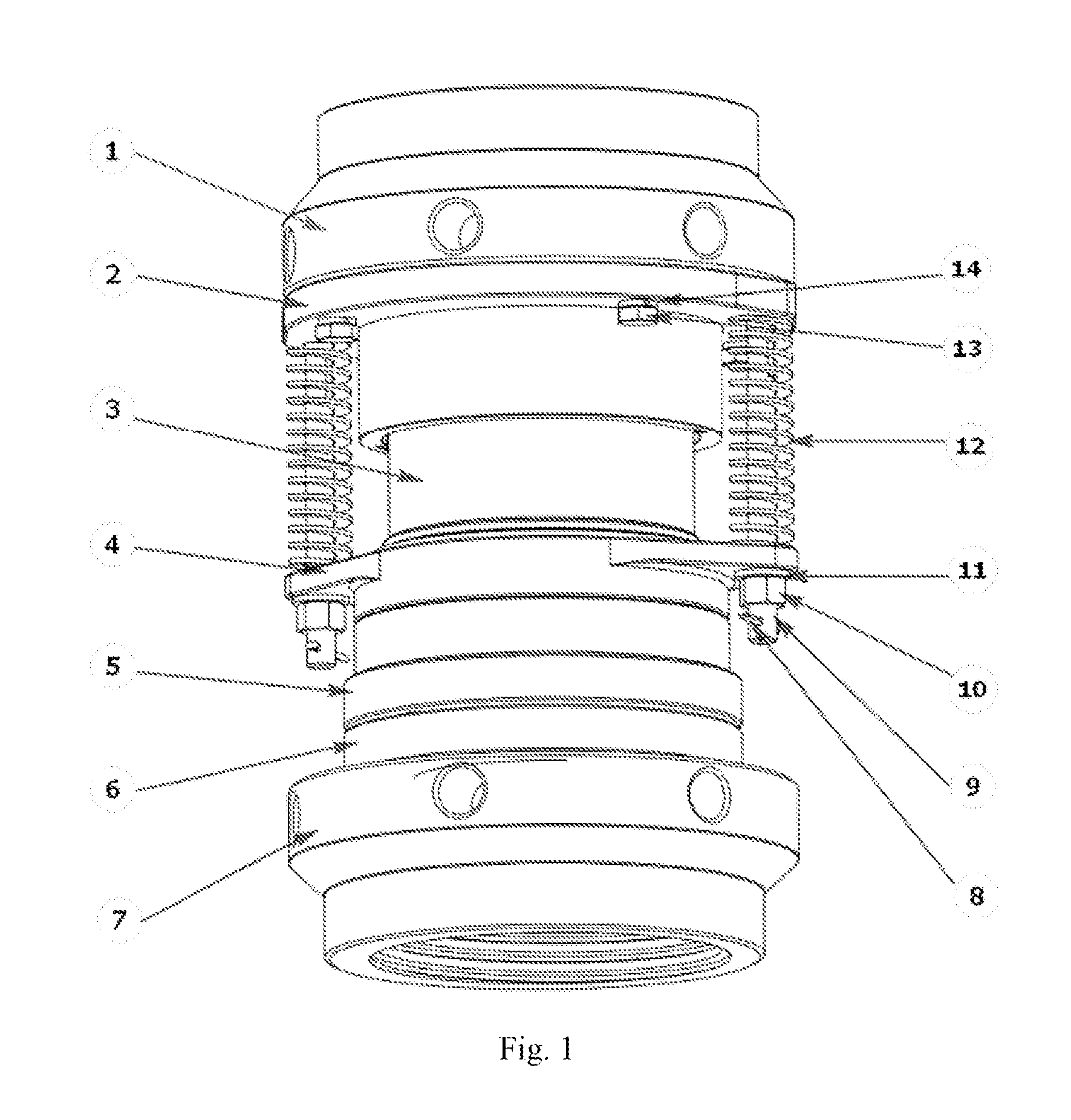
[0028]Refer to FIG. 1 and FIG. 2, it is illustrated a preferred embodiment of the present invention which relates to a washpipe assembly incorporating an upper union 1, a floating seal assembly secured to said upper union 1, a stationary seal ring 5 attached to said floating seal assembly, a lower union 7, a rotating seal ring 6 attached to said lower union 7, and a washpipe 15 suspended inside and between said upper union 1 and said floating seal assembly th...


PUM


Abstract

A washpipe assembly is described for a passage of pressurized drilling fluid from a stationary first conduit member to a rotating second conduit member. The washpipe assembly comprises a lower union secured to the rotating second conduit member, an upper union secured to the stationary first conduit member, a floating seal assembly attached to the upper union, a rotating seal ring attached to the lower union, and a stationary seal ring attached to the floating seal assembly. The washpipe assembly also includes a washpipe suspended inside the upper union and the floating seal assembly through a waveform snap ring.

Description

BACKGROUND OF THE INVENTIONField of the Invention[0001]This application is related to a rotary seal assembly permitting a passage of high pressure fluid in the field of oil and gas drilling operations, particularly, to a washpipe assembly used in oil and gas drilling equipment, such as a drilling rig swivel, or a top drive.Description of the Related Art[0002]A washpipe device, which is utilized to provide a rotary passage between a gooseneck and a main shaft in order to deliver high pressure drilling fluid from mud pumps to a drilling bit, is one of the most important members of a drilling rig swivel or a top drives in oil and gas drilling operations. In particular, a washpipe assembly, which is easy to install and maintain, and which is operational with high pressure and of a long working life, contributes safety and efficiency of oil and gas operations.[0003]There are two types of washpipe assembly, the traditional washpipe assembly which utilizes a stack of elastomeric rotary sea...

Claims


Application Information

Patent Timeline
Patent Type & Authority Applications(United States)
IPC IPC(8): E21B17/05E21B21/02
CPCE21B21/02E21B17/05
Inventor LI, XUEJUNLIU, CHENCUI, JIE
Owner BEIJING JJC PETROLEUM EQUIP
Learn More