
Method and apparatus for proving an authentication of an original item and method and apparatus for determining an authentication status of a suspect item

a technology for authenticating original items and suspect items, applied in the direction of instruments, electric digital data processing, sensing record carriers, etc., can solve the problems of large databases, impede the industrial implementation of authenticating documents, and complicate the generation of authenticating documents

Active Publication Date: 2016-11-24
THYMARIS LTD
View PDF2 Cites 16 Cited by
  • Summary
  • Abstract
  • Description
  • Claims
  • Application Information

AI Technical Summary

Benefits of technology

The patent describes a way to quickly and easily determine the authentication status of a suspect item using optical systems. This method and apparatus can be used in industrial facilities, like pharmaceutical plants, where barcodes are printed onto items for serialization. The advantage of using optical systems is that they require lower resolution and fewer adaptations to existing systems. The method also allows for fast and accurate identification of the suspect item through a database record related to the authentication of the item. This reduces the possibility of false-positive or false-negative identification.

Problems solved by technology

The first concepts for determining these kinds of structures, however, had to struggle with various barriers which mainly concerned the processing and storing of data related to the authentication status.
However, both the technological barriers concerning the reproducibility of the recognition of unique features as well as the insufficient storing capabilities led to a security problem which complicated the generation of authenticatable documents.
As a result, this kind of procedure generates large databases which have to be searched completely during an authentication process.
Although various methods and devices for determining the authentication status of a suspect item have been proposed, still, a number of problems and obstacles exist which particularly impede their industrial implementation on a larger scale.
Within this regard, a major issue relates to the resolution of optical systems which are employed in the acquisition of print images such as one- or two-dimensional barcodes.
As a result, devices which are already installed for the decoding of barcodes do not exhibit a sufficient resolution which would allow employing such devices for the recognition of irregularities in the margins of a print image at the same time.
In addition, such methods and devices for determining the authentication status of a suspect item require a high sharpness of the print image.
This would require a high illumination which is rather sophisticated and lead to a large heat generation which could heat up the object to intolerable values.
Consequently, methods and devices for determining the authentication status of a suspect item which are based on margin recognition are currently not compatible with the requirements in industrial facilities.
Second, the surface of the item may not allow the consistent placing of the printed version of the code, e.g. in a case where the surface is too rough or too impermanent for consistently carrying the printed version of the code.
Fourth, there may also be legal or statutory reasons which may require the item to be furnished with a packaging, such as for medical drugs.
On the other hand, the counterfeit may be accomplished in a quality that the suspect item may not show any such evidence which would make it distinguishable from the original item in this way.
Consequently, each printing technology as applied by the original printing device may leave a kind of fingerprint resulting from printing the printed version of the code onto the original item.
In practice, it may turn out to be virtually impossible to generate two identical printed versions of the same ideal image based on the same code.
However, since this and other standard have been generated for other purposes, they may not provide optimal results when being employed within the methods according to the present invention.
However, step iii) may particularly concentrate on errors which randomly occur within the picture of the printed version of the code under investigation.
Within a further aspect, the printing device may have at least one clogged nozzle, which may result in a missing line along the printed area within at least one of the modules in the picture of the printed version of the code.
Within a further aspect, vibrations may occur during the printing process which may cause a distorted image in at least one affected module in the picture of the printed version of the code with respect to the ideal image, which may result in an amended filling of the area in the affected module.
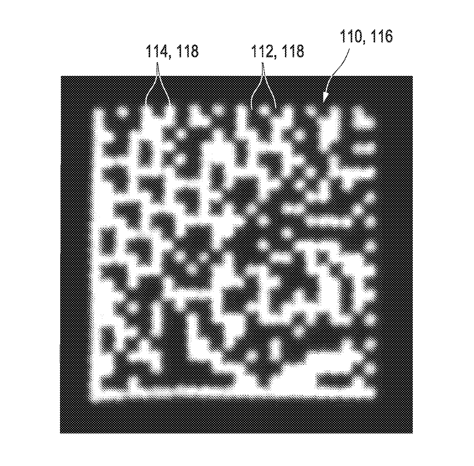
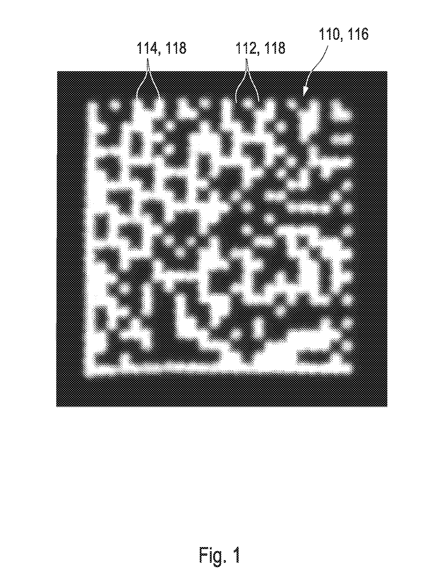
Whereas the ideal image comprises no deviations, the printing process might induce some irregularities which may result in deviations be observable in the picture of the printed version of the code.
Although this kind of procedure may result in a slightly higher data volume as required for storing larger numerical values as the individual imperfection profiles, which might, however, not be relevant in an era of huge and cheap data storage devices.
In case of a poor quality and / or a low resolution of the picture of a printed version of the code, the present authentication method may provide distorted results, such that a copy of the code may be mistaken for a genuine code one or vice-versa.
Surprisingly, it has been found that the existing procedures for image processing may not deliver the required results for pictures of a printed version of the data matrix barcode, since these procedures may generally not be adapted for the characteristics of the data matrix barcode, in particular, not to its binary nature.
In addition, blurring may usually occur due to an aberration caused by recording an image being out of focus.
However, these kinds of optical systems currently used for ensuring barcode quality, are not able to be employed in any authentication method according to the state of the art.
In addition, this advantage particularly may reduce the requirements for a discriminability of authentication data and, at the same time, may decrease the possibility of a false-positive or a false-negative identification.

Method used


Image

  • Method and apparatus for proving an authentication of an original item and method and apparatus for determining an authentication status of a suspect item
  • Method and apparatus for proving an authentication of an original item and method and apparatus for determining an authentication status of a suspect item
  • Method and apparatus for proving an authentication of an original item and method and apparatus for determining an authentication status of a suspect item

Examples


second embodiment

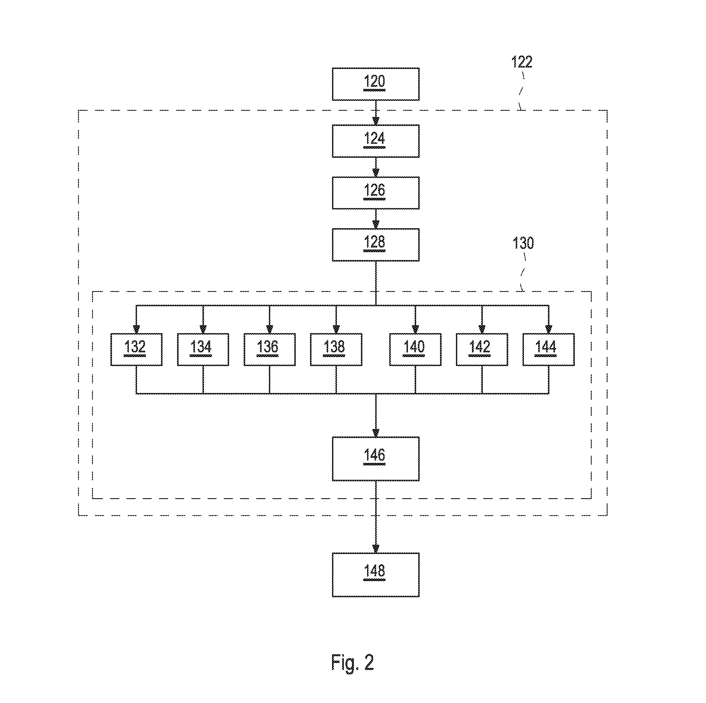
[0286]According to FIG. 15B, within the second preferred embodiment for determining the authentication status of 172 the suspect item only the recording step 124, the modifying step 126, and the decoding step 128, may be performed locally until the modified picture 110 of the printed version of the code is transmitted within the transmission step 166 to the data processing unit via the computer network, where the remaining steps, including the analyzing step 130, the calculating step 132, the selecting step 168, the comparing step 170, and the returning step 174 may be performed. By this procedure, the second embodiment may provide the authentication status 172 of the suspect item.

[0287]Summarizing as described in FIG. 15B, the second preferred embodiment for the method for determining the authentication status 172 of the suspect item 180 may comprise the following steps:[0288]124 Recording step: recording the picture 110 of the printed version of the data matrix barcode printed ont...

third embodiment

[0297]Finally, a third embodiment as schematically depicted in FIG. 15C may also provide the authentication status 172 of the suspect item. In this particular embodiment, only the recording step 124 may locally be performed before the picture 110 of the printed version of the code may be transmitted, with the transmission step 166, to the data processing unit via the computer network, whereas the remaining steps, including the modifying step 126, the decoding step 128, the analyzing step 130, the calculating step 132, the selecting step 168, the comparing step 170, and the returning step 174 may be performed.

[0298]Summarizing as described in FIG. 15C, the third preferred embodiment for the method for determining the authentication status 172 of the suspect item 180 may comprise the following steps:[0299]124 Recording step: recording the picture 110 of the printed version of the data matrix barcode printed onto the item by means of an optical system;[0300]166 Transmission step: trans...

first embodiment

[0309]FIG. 16 schematically depicts a preferred authentication apparatus 176 which is configured for performing the method for determining the authentication status 172 as schematically presented in FIG. 15A. Here, a recording device 178 may, according to part A), be configured for recording the picture 110 of the printed version of a data matrix barcode which may have been printed onto an item 180, such as a bottle which might comprise a pharmaceutical preparation. Hereby, the recording of the picture 110 may be supported by a light source 182 which may illuminate the picture.

[0310]The authentication apparatus 176 may, according to part B), further comprise a decoding device 184 which may be configured for decoding the at least one barcode content from the picture 110 of the printed version of the code according to the set of rules applicable to the data matrix barcode. A further part of the authentication apparatus 176 may, according to part C), be the analyzing device 186 config...


PUM


Abstract

An apparatus and method for authenticating an item wherein a code is assigned to the item and includes a plurality of modules arranged in an ideal image. A barcode is encoded within the modules and a picture of the code is printed onto the item. A picture of the printed code is recorded with a low resolution camera at high speed during the production process from which the barcode content is decoded. Irregularities in the picture are analyzed and a numerical value describing an individual imperfection profile is calculated. The numerical value of the imperfection profile depends on at least one unique feature inherently related to the original printing device. The individual imperfection profile is printed onto the item and / or a database record is generated. To authenticate a suspect item, the imperfection profile of the suspect item is compared with the imperfection profile of the original item.

Description

CROSS REFERENCE TO RELATED APPLICATIONS[0001]This is a continuation of application serial no. PCT / EP2015 / 052046 filed Feb. 2, 2015 which claims priority from EP 14 153 785.2 filed Feb. 4, 2014 and from EP 14 185 775.5 filed Sep. 22, 2014 the disclosures of all three of which are hereby incorporated by reference.BACKGROUND[0002]1. Technical Field[0003]The present disclosure relates to a method, an apparatus and a use of an apparatus for proving an authentication of an original item as well as to a hereto related method and apparatus for determining an authentication status of a suspect item. The disclosure further relates to a computer program for performing the mentioned methods as well as to a data carrier having a data structure stored thereon, which, after loading into a computer or a computer network, is capable of executing the methods.[0004]2. Description of the Related Art[0005]The proof of the authentication of an original item as well as the determination of the authenticat...

Claims


Application Information

Patent Timeline
IPC IPC(8): G06K19/10G06F17/30G06K7/14G06Q30/00G06K19/06G06K7/10
CPCG06K19/10G06K19/06037G06K7/10732G06K7/1417G06K7/1473G06F17/30268G06K7/1443G06K7/1452G06K7/1456G06Q30/018G06V20/80G06V20/95G06F16/5866
Inventor TOEDTLI, SERGEJTOEDTLI, SASCHATHIBAULT, YOHAN
Owner THYMARIS LTD
Learn More