Hydraulic turbine

Active Publication Date: 2016-11-10
NATEL ENERGY
View PDF11 Cites 3 Cited by
  • Summary
  • Abstract
  • Description
  • Claims
  • Application Information

AI Technical Summary

Benefits of technology

The present invention is about converting the energy of a flowing fluid into shaft work. It provides an improved system for a linear hydraulic cross-flow turbine that has the benefits of conventional free jet cross-flow turbines, such as high efficiency and self-cleaning operation, but also offers significant improvements in specific speed, efficiency, and design freedom. The turbine has two working stages where the blades move in substantially linear paths around a central array of stationary guidevanes. It effectively maximizes the "working zone" in the turbine and minimizes the portion of the flow that becomes "entained" in the vanes, resulting in higher efficiency compared to conventional circular cross-flow turbines. The disclosed design can be built with a true free-jet nozzle, which allows for instantaneous de-powering of the turbine in the event of a grid fault. This design can significantly reduce the total cost of hydropower plants.

Problems solved by technology

Also this crossing flow can be well-conditioned with little turbulence, while in a circular cross-flow turbine the theoretical flow path actually crosses through itself, and also may collide with the necessary drive shaft, creating additional losses.
Furthermore, a significant fraction of the flow in a circular cross-flow turbine becomes “entrained” in the vanes circumferentially, contributing to a loss in performance.
These types of surge loads often are so large that they drive the design of the penstock and other pipeline equipment.

Method used


Image

  • Hydraulic turbine
  • Hydraulic turbine
  • Hydraulic turbine

Examples


Embodiment Construction

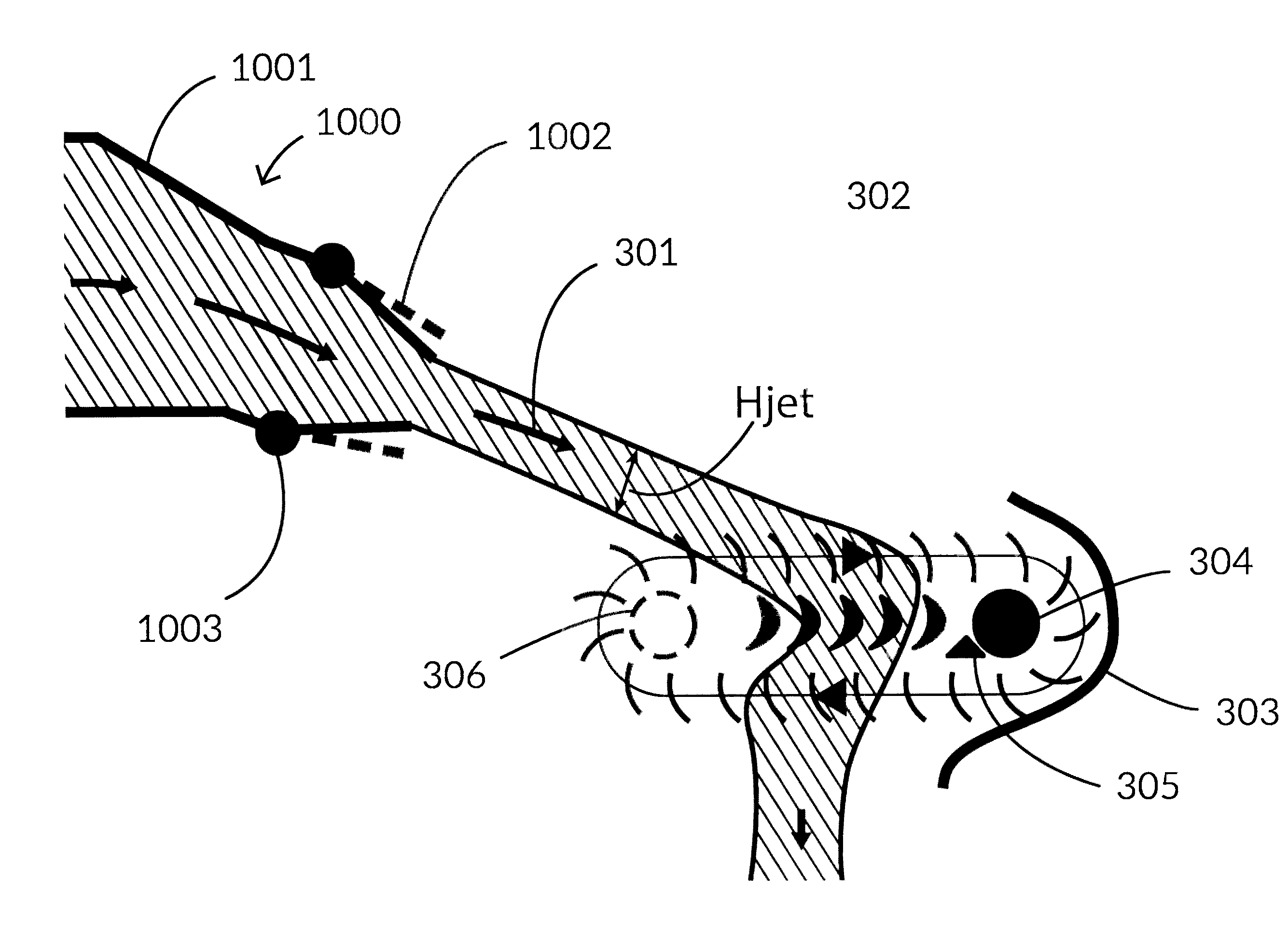
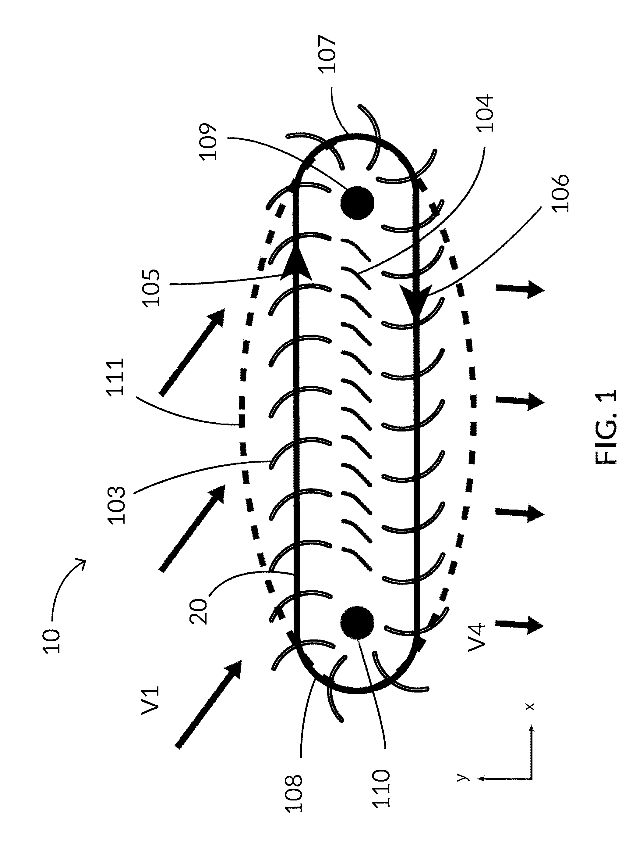
[0138]As shown in FIG. 1, a turbine 10 can include a first axis 109 and a second axis 110. First axis 109 and second axis 110 can be parallel. First axis 109 and second axis 110 can be spaced along a horizontal direction. In another aspect, first axis 109 and second axis 110 can be spaced along a vertical direction. In another aspect, first axis 109 and second axis 110 can be spaced along a plane at some angle relative to horizontal, between horizontal and vertical.

[0139]The turbine 10 can include blades 103 that can move in a path consisting of multiple segments between and around first axis 109 and second axis 110. For example, blades 103 can move through a first segment 105 from second axis 110 toward first axis 109, a second segment 107 around first axis 109, a third segment 106 from first axis 109 toward second axis 110, and a fourth segment 108 around second axis 110. After fourth segment 108, blades 103 can re-enter first segment 105. First segment 105 and third segment 106 c...


PUM


Abstract

Disclosed herein are linear hydraulic turbines in which the linear machine converts the majority of available energy in the flowing water into useful torque directly in the runner, leaving the outflow with very little velocity.

Description

CROSS-REFERENCE TO RELATED APPLICATION[0001]This application claims the benefit of U.S. Provisional Patent Application No. 62 / 158,170, filed May 7, 2015, which is incorporated herein by reference in its entirety.BACKGROUND[0002]Cross-flow turbines with circular cross-section are commonly known and have been widely used in hydropower applications around the world for many decades.[0003]This type of turbine operates on a free-jet principle, utilizing a nozzle to direct high velocity fluid flow through a runner. This runner can consist of multiple blades of circular arc section arrayed about a single axis, comprising in their entirety a cylindrical shape. Water flows through the cylinder in a direction perpendicular to the cylinder axis, so that the fluid performs work on two different areas of the circumferential blades. By design, this type of turbine extracts most of the kinetic energy in the flowing water within the two stages of the turbine, and because the exhausted water has lit...

Claims


Application Information

Patent Timeline
IPC IPC(8): F03B7/00F03B3/04F03B11/06F03B11/02F03B13/10
CPCF03B7/006F03B11/02F03B3/04F03B11/06F03B13/10F05B2240/12F05B2240/1231F05B2240/13F05B2240/244F05B2220/32F05B2240/123Y02E10/20Y02E10/30F03B1/02F03B1/04F03B11/004
Inventor SCHNEIDER, ABRAHAM D.
Owner NATEL ENERGY
Why Eureka
Try Eureka