
Golf ball spin axis measurement

Active Publication Date: 2016-10-20
EDH US
View PDF0 Cites 21 Cited by
  • Summary
  • Abstract
  • Description
  • Claims
  • Application Information

AI Technical Summary

Benefits of technology

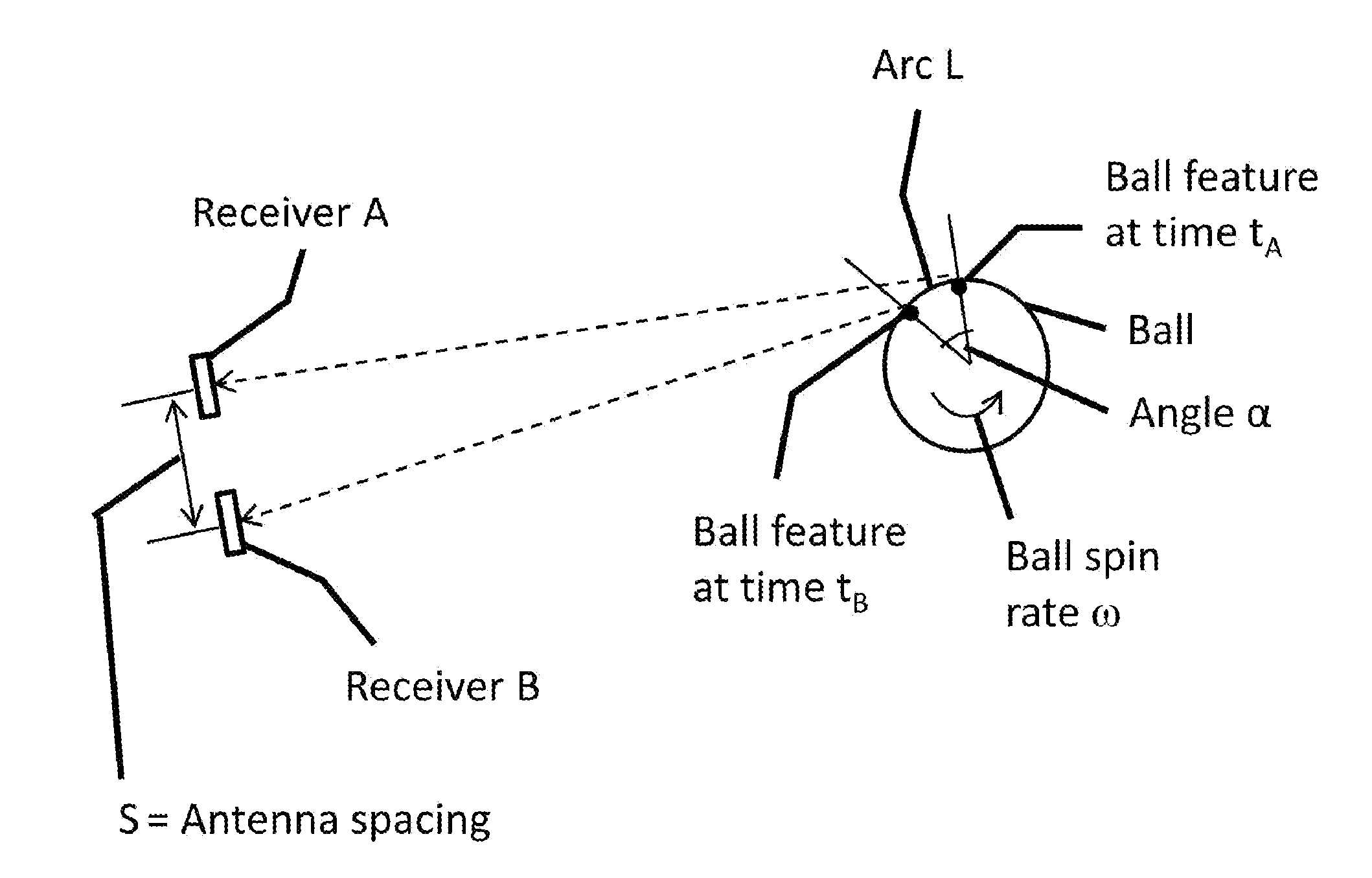
The patent text describes analyzing signals to determine the time differences between two vertical and two horizontal receivers. If four receivers are used, this setup provides two independent measurements in both the horizontal and vertical directions, resulting in improved statistical accuracy. In simpler terms, the patent text is about using multiple receivers to get more accurate data.

Problems solved by technology

It is difficult to determine golf ball spin axis through direct measurement.
This method is limited in that it has to observe the ball flight for an extended time period (not possible in an indoor test environment or fitting studio), and is affected by wind which disturbs the trajectory, and radar alignment errors.
Cameras are generally poor at measuring high speed objects such as moving golf balls.
High speed cameras are costly and suffer from difficulties in alignment, illumination, and measurement reliability.
Current methods also usually involve determining complex three-dimensional movement from limited and blurred two-dimensional images, leading to inaccurate results or even failing to provide a result.

Method used


Image

  • Golf ball spin axis measurement
  • Golf ball spin axis measurement
  • Golf ball spin axis measurement

Examples


Embodiment Construction

[0025]The following is a detailed description of illustrative embodiments of the present invention. As these embodiments of the present invention are described with reference to the aforementioned drawings, various modifications or adaptations of the methods and or specific structures described may become apparent to those skilled in the art. All such modifications, adaptations, or variations that rely upon the teachings of the present inventions, and through which these teachings have advanced the art, are considered to be within the spirit and scope of the present invention. Hence, these descriptions and drawings are not to be considered in a limiting sense, as it is understood that the present invention is in no way limited to the embodiments illustrated.

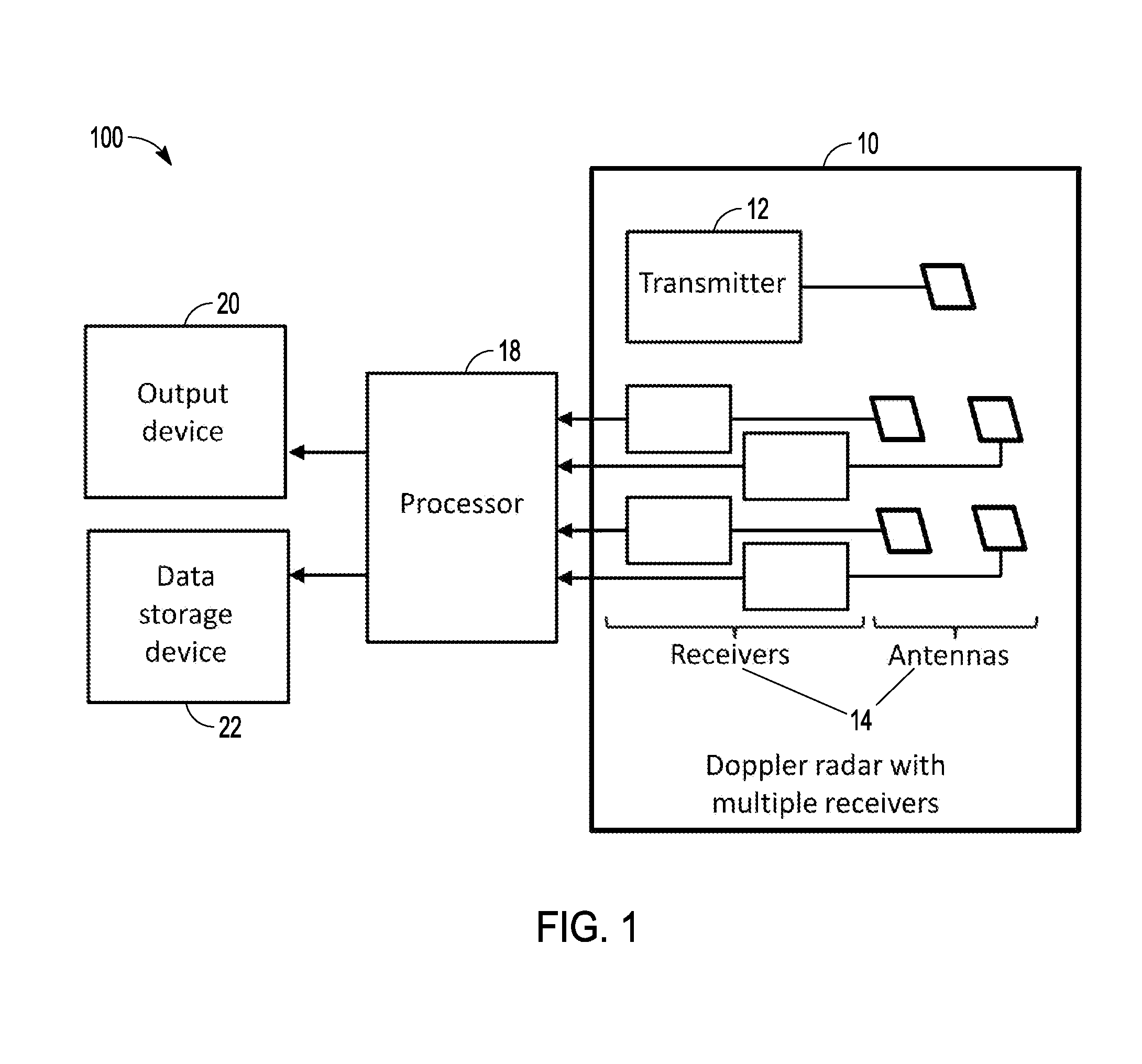
[0026]Viewed broadly, an example system and method to measure a ball spin axis includes the following components and / or steps: a Doppler radar with multiple receiver channels, a processor, a launched golf ball, receiving reflecte...


PUM


Abstract

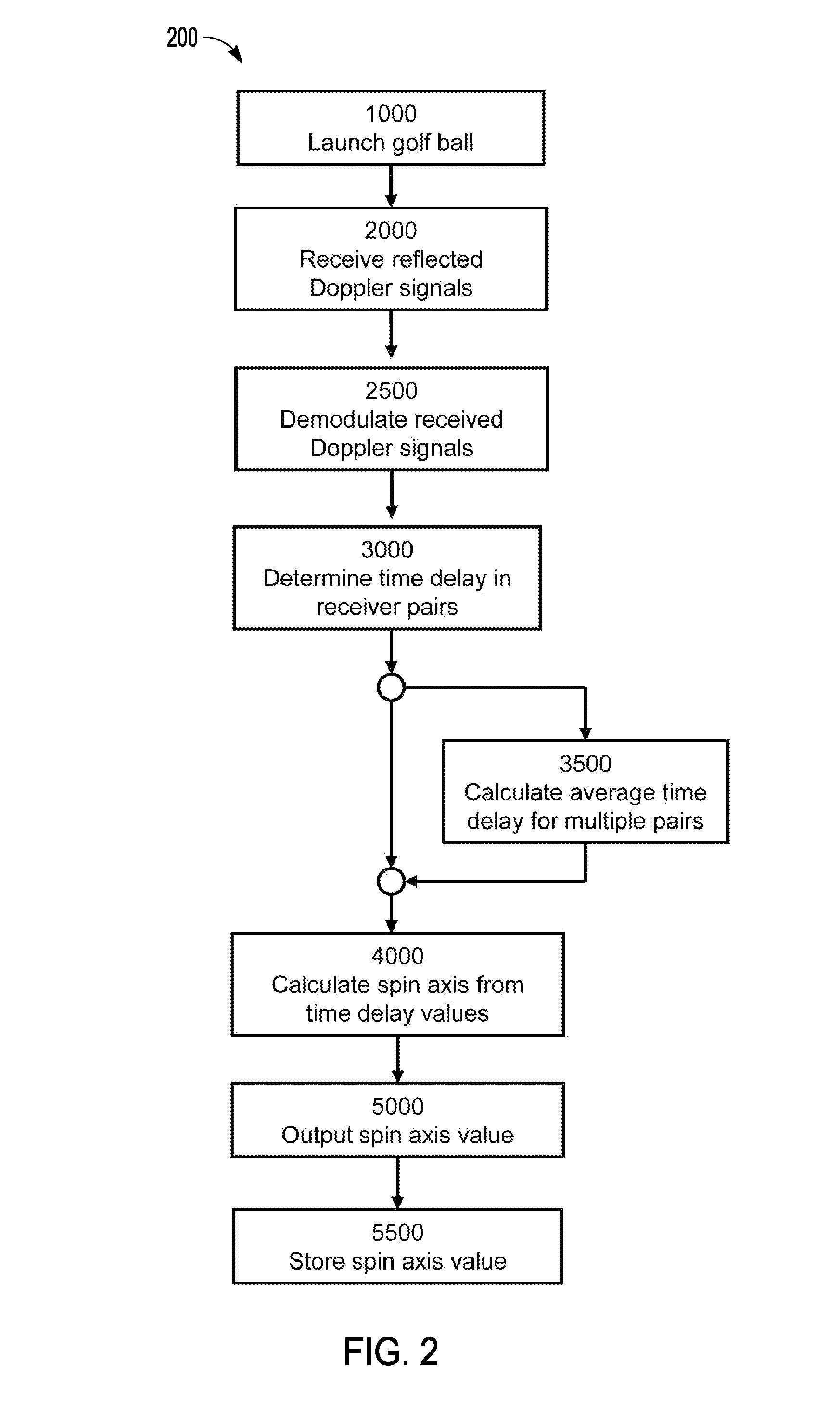
Systems, methods and media are provided for golf ball spin axis measurement. In one example, a method comprises detecting a launched golf ball, receiving reflected Doppler signals from the golf ball by a radar device having an array of multiple receiver pairs, demodulating the spin-induced signals from the received signals, determining a time delay between the demodulated signals for the receiver pairs in the array, calculating an average time delay for the multiple receiver pairs, calculating a spin axis of the golf ball from the time delay values, outputting a spin axis value to an external system, and storing the spin axis value in a database.

Description

RELATED APPLICATIONS[0001]This application claims priority from U.S. Provisional Patent Application Ser. No. 61 / 911,404, filed Dec. 3, 2013, which is incorporated herein by reference in its entirety and made a part hereof.BACKGROUND[0002]It is difficult to determine golf ball spin axis through direct measurement. This disclosure provides a means and method to measure golf ball spin axis directly by making use of an appropriately spaced array of Doppler radar receivers.[0003]Conventionally, the flight path of a golf ball is determined mainly by its launch speed, launch angle relative to the horizontal, and spin. Golf ball spin is caused by using a lofted club with a grooved club face. Spin imparts aerodynamic forces on a ball due to the interaction between the dimpled surface of the ball and the surrounding air fluid. In a golf ball, a lifting force opposite to gravity causes the ball to stay airborne longer and allowing a golfer to achieve greater carry distances than if no such for...

Claims


Application Information

Patent Timeline
IPC IPC(8): G01S13/58
CPCG01S13/58G01S13/878G01S13/88
Inventor JOHNSON, HENRI
Owner EDH US
Learn More