
An apparatus and method for particulate capture from gas streams and a method of removing soluble particulate from a gas

a technology of soluble particulate matter and gas stream, which is applied in the direction of dispersed particle separation, organic chemistry, separation processes, etc., can solve the problems of difficult removal of urea dust, low concentration of urea dust, and high operating costs of pollution control equipmen

Active Publication Date: 2016-10-20
STAMICARBON BV
View PDF25 Cites 20 Cited by
  • Summary
  • Abstract
  • Description
  • Claims
  • Application Information

AI Technical Summary

Benefits of technology

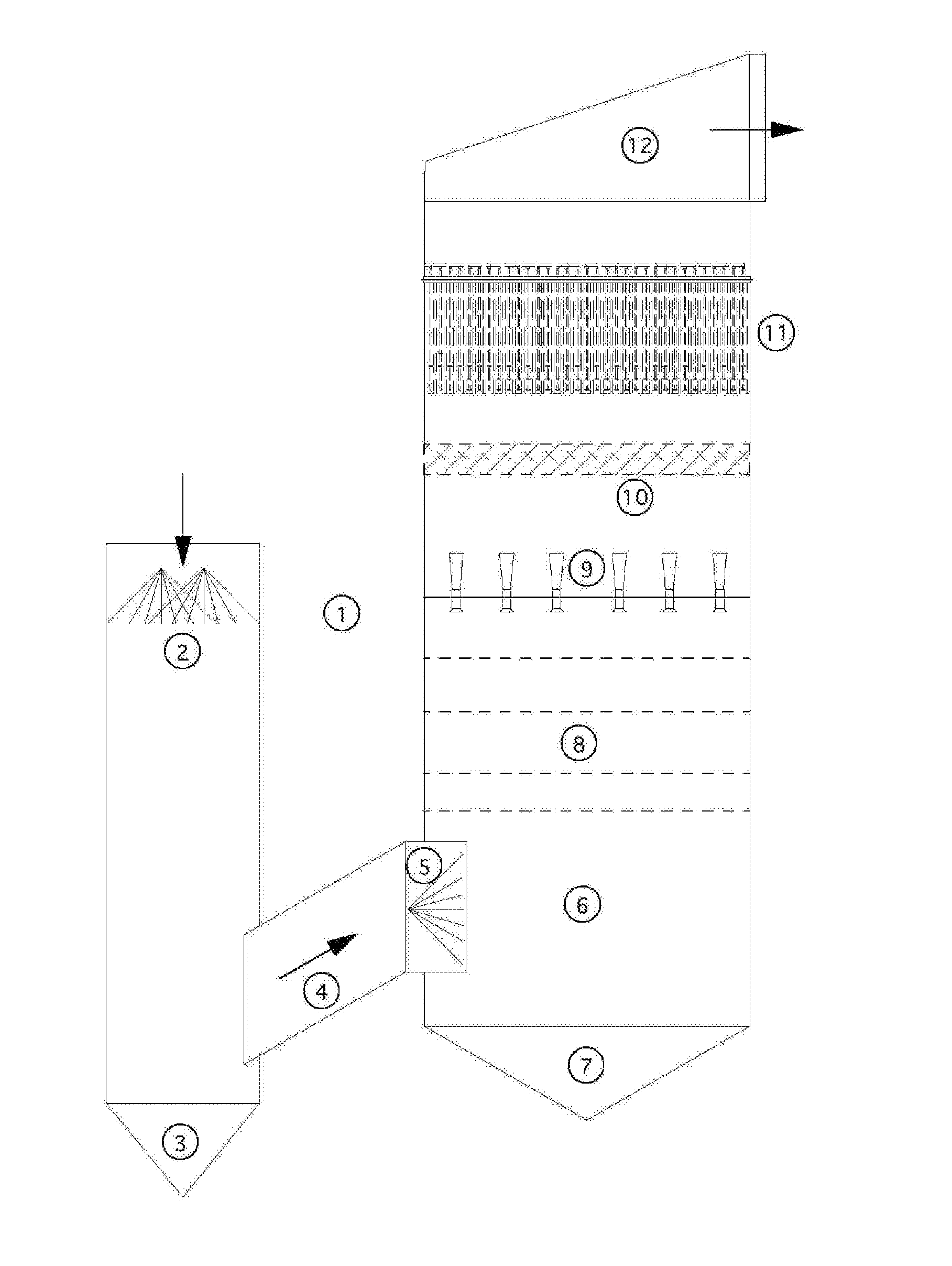
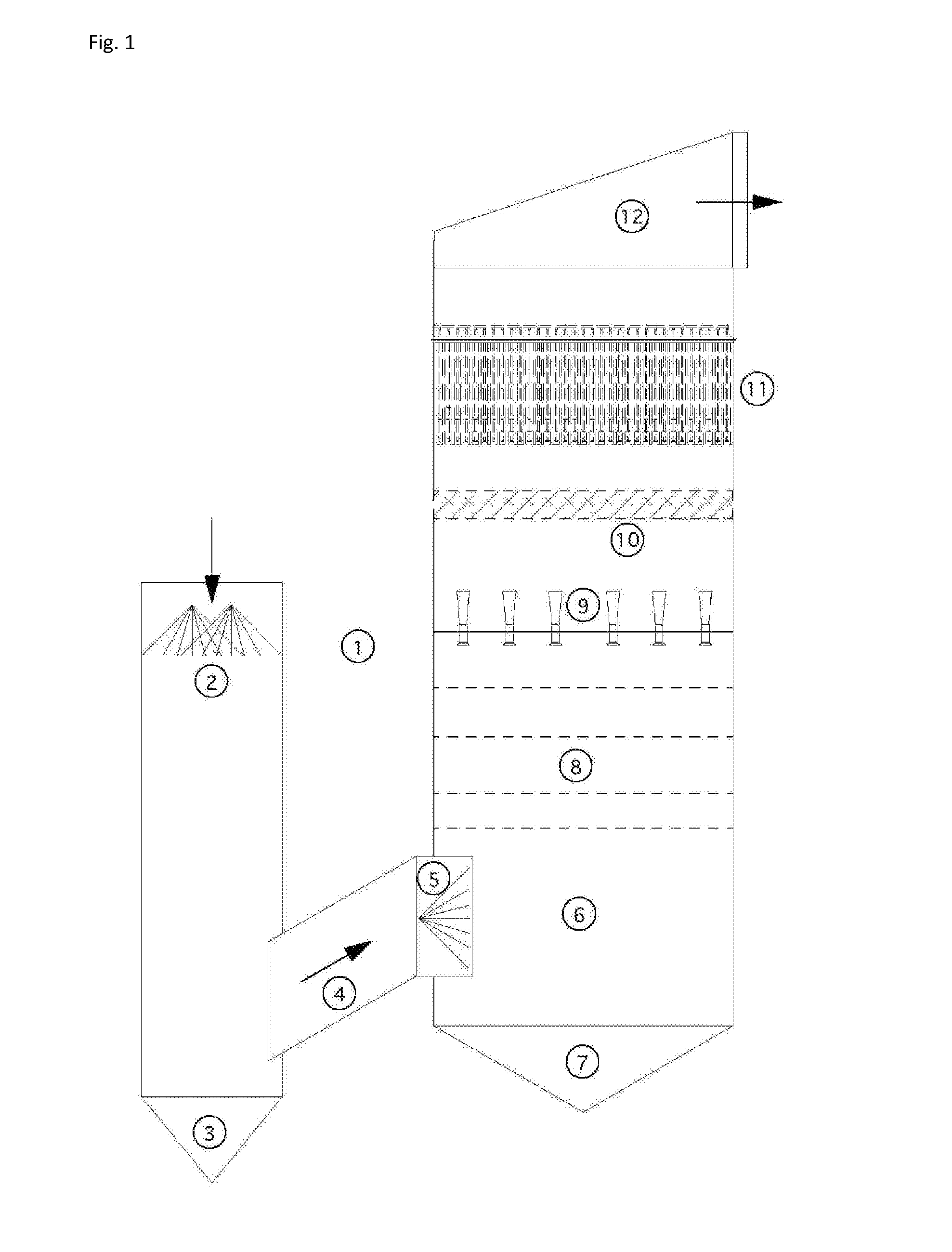
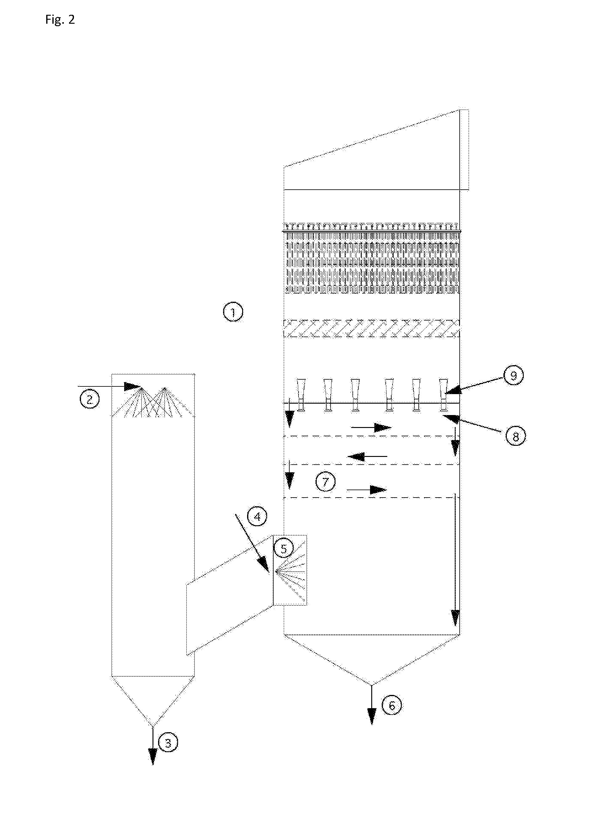
The present invention relates to a method for the removal of soluble particulate matter from a gas stream, which comprises subjecting the gas stream to quenching with an aqueous quenching liquid and passing it through at least one particle capture zone. The gas stream is treated in stages with different quenching liquids, where the downstream quenching liquid has a lower concentration of dissolved particles than the upstream quenching liquid. The invention also provides a particle capture system and a method for modifying an existing urea plant by installing one or more quenching systems between the finishing section and the dust scrubbing section. The quenching systems can operate independently of each other and form part of recirculation loops. The technical effects of the invention include improved gas purification, reduced emissions of soluble particles, and improved efficiency of urea production and finishing.

Problems solved by technology

These drawbacks led to the development of the fluidized bed granulation technique, where the urea melt is sprayed on granules that grow in size as the process continues.
In addition, the operating costs of running pollution control equipment can be substantial, and so there is also a constant demand for financially efficient technologies.
The removal of urea dust is challenging per se, since the amounts of off-gas (mainly air) are enormous, while the concentration of urea dust is low.
A further problem is that the large amounts of air needed in urea finishing, results in this part of the production process being a relatively costly effort due to the need for very large extractor fans having large electricity consumption.
Particularly, when the air is subjected to scrubbing in order to reduce the emission of urea dust, and specifically a major part of the submicron dust, into the atmosphere, a relatively large amount of energy is simply lost in the process, as a result of the inevitable pressure drop in the scrubbing device.
Tray scrubbers do not effectively capture submicron particulate.
However, WESPs suffer from operational problems.
When there is high particulate loading, flushing must be done often and results in high emissions.
When insufficient washing occurs, particulate builds up and creates sparking zones that are difficult to remove, leading to a degradation in performance over time, outages for cleaning, and corrosion problems.
These small particles are difficult to collect in conventional scrubbers due to their size.
Once released to the atmosphere, particulate and nitrogen oxides can produce opacity and respiratory problems and sulfur dioxide reacts slowly to form sulfuric acid (H2SO4), inorganic sulfate compounds, and organic sulfate compounds.
Atmospheric NO2, SO2, or H2SO4 results in undesirable “acid rain.”

Method used


Image

  • An apparatus and method for particulate capture from gas streams and a method of removing soluble particulate from a gas
  • An apparatus and method for particulate capture from gas streams and a method of removing soluble particulate from a gas
  • An apparatus and method for particulate capture from gas streams and a method of removing soluble particulate from a gas

Examples


example 1

[0092]A urea granulator is proposed that has a urea-laden off-gas that needs to be scrubbed. The temperature of the air leaving the granulator is 100.5° C. and the molar fraction of water vapor is 3.1%. A quencher spray is proposed which will cool the air by evaporation until the airflow is saturated and water no longer evaporates. Using thermodynamic calculations in combination with steam tables, it is determined that this will occur at a final gas temperature of 37.2° C. with a water vapor molar fraction of 6.4% when using pure water. For this proposed project the amount of water evaporated is calculated to be 4.61 L / s. However, in practice, the quench spray will be recirculated until the urea concentration increases to around 45% by weight. At this urea concentration, the vapor pressure of water is much less. Using Raoult's Law as an estimate, the above calculations are repeated to find that the new saturated gas temperature is 39.4° C. with a water vapor molar fraction of 5.8%. ...

example 2

[0093]In a scrubber installed with only one quench, sodium sulfate is captured from the exhaust gas of a recovery boiler at a paper mill that is 221° C. with 30% moisture. When the quench water is refreshed and the concentration of sodium sulfate is kept low, the calculated saturation temperature is 74° C. with 36.5% water vapor in the gas phase. However, the paper mill prefers to cycle up the concentration of the sodium sulfate to a Baume of 16%. At this concentration, the saturation temperature climbs to 76° C. with only 36.2% moisture in the gas phase. This creates a situation where downstream evaporation continues and submicron particulate is not grown in size sufficiently. Under high Baume conditions, particulate emissions increase. A second fresh (or dilute) water quench would increase particle capture performance of the scrubber.


PUM

PropertyMeasurementUnit
diameteraaaaaaaaaa
diameteraaaaaaaaaa
RHaaaaaaaaaa

Abstract

Disclosed is a method for the removal of soluble particulate matter from a gas stream, such as urea dust from the off-gas of a finishing section of a urea production plant. The method comprises subjecting the off-gas to at least two quenching stages an aqueous quenching liquid. The quenching liquid used in a first, upstream quench stage, is allowed to have a higher concentration of dissolved particulate matter than the quenching liquid in the second, downstream quench stage. The quenched gas is led through a particle capture zone, typically comprising one or more of a wet scrubber, a Venturi scrubber, and a wet electrostatic precipitator.

Description

FIELD OF THE INVENTION[0001]The invention is in the field of the capture of soluble particulate matter from gas streams, and relates to particle capture devices that can be used therein. Notably, the invention is in the field of urea production, and pertains to the removal of urea dust from the off-gas associated with the production of solid urea particles (urea finishing). The invention also pertains to a urea production plant, and to revamping an existing urea production plant.BACKGROUND OF THE INVENTION[0002]Urea is produced from ammonia and carbon dioxide. Today's urea production involves relatively clean processes, particularly low in the emission of urea dust and ammonia. However, besides the chemical synthesis of urea, the production of urea on a commercial scale requires that the urea be presented in a suitable solid, particulate form. To this end, urea production involves a finishing step in which a urea melt is brought into the desired particulate form, generally involving...

Claims


Application Information

Patent Timeline
Patent Type & Authority Applications(United States)
IPC IPC(8): B01D47/12B03C3/013B01D47/05B01D47/10
CPCB01D47/12B01D47/05B03C3/013B01D47/10B01D47/06C07C273/16B01D2247/103B01D2247/102B01D2247/04B01D2247/107B01D2251/506B01D2252/103B01D53/58
Inventor HIGGINS, BRIAN SAYRE
Owner STAMICARBON BV
Learn More