
Tubular resonant filter and method of making a tubular resonant filter

a tubular resonant filter and tube resonant technology, applied in the field of filters, can solve the problems of large footprint, difficult to integrate on-chip monolithically, and serious shortcomings of state-of-the-art technologies, and achieve the effect of relieving strain in the strained layer

Active Publication Date: 2016-10-13
THE BOARD OF TRUSTEES OF THE UNIV OF ILLINOIS
View PDF3 Cites 7 Cited by
  • Summary
  • Abstract
  • Description
  • Claims
  • Application Information

AI Technical Summary

Benefits of technology

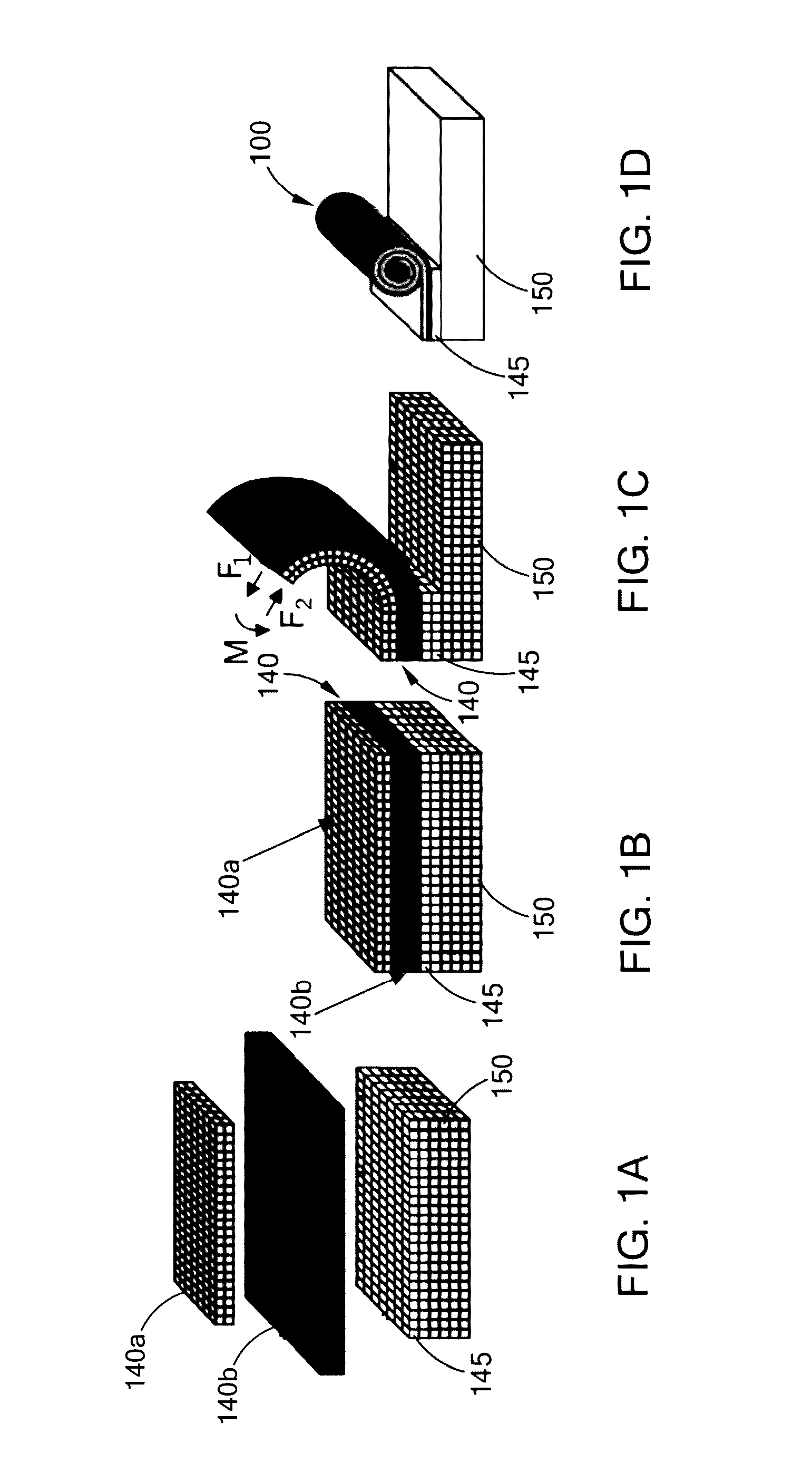
The patent text describes a new type of filter used in RFICs that solves problems with existing filters. The filter is made up of a special layered structure that includes a strain-relieved layer, a patterned conductive layer, an insulating layer, and another patterned conductive layer. The layers are rolled up together to form a resonant circuit that can improve the performance of filters used in RFICs. The method of making the filter involves forming a sacrificial layer, straining the layer with an upper layer under tension and a lower layer under compression, adding a patterned conductive layer, adding an insulating layer, adding another patterned conductive layer, and then removing the sacrificial layer to allow the strained layer to move away from the substrate and roll up to relieve strain. The final result is a unique filter that can enhance the performance of RFICs.

Problems solved by technology

Although filters have been researched for decades, state-of-the-art technologies have serious shortcomings that have proven difficult to overcome.
For example, lumped element filters cannot be used at frequencies above X band (˜8.0-12.0 GHz), and distributed filters suffer from a large footprint and are therefore hard to integrate on-chip monolithically.
In addition, the performance of state-of-the-art filters may be severely limited by substrate losses caused by electric and magnetic couplings between the resonator and substrate.

Method used


Image

  • Tubular resonant filter and method of making a tubular resonant filter
  • Tubular resonant filter and method of making a tubular resonant filter
  • Tubular resonant filter and method of making a tubular resonant filter

Examples


Embodiment Construction

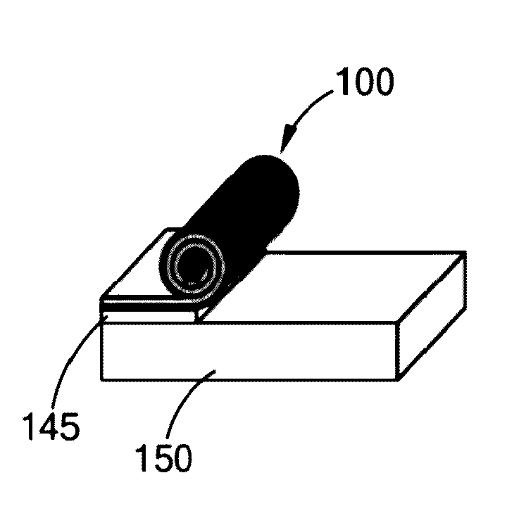
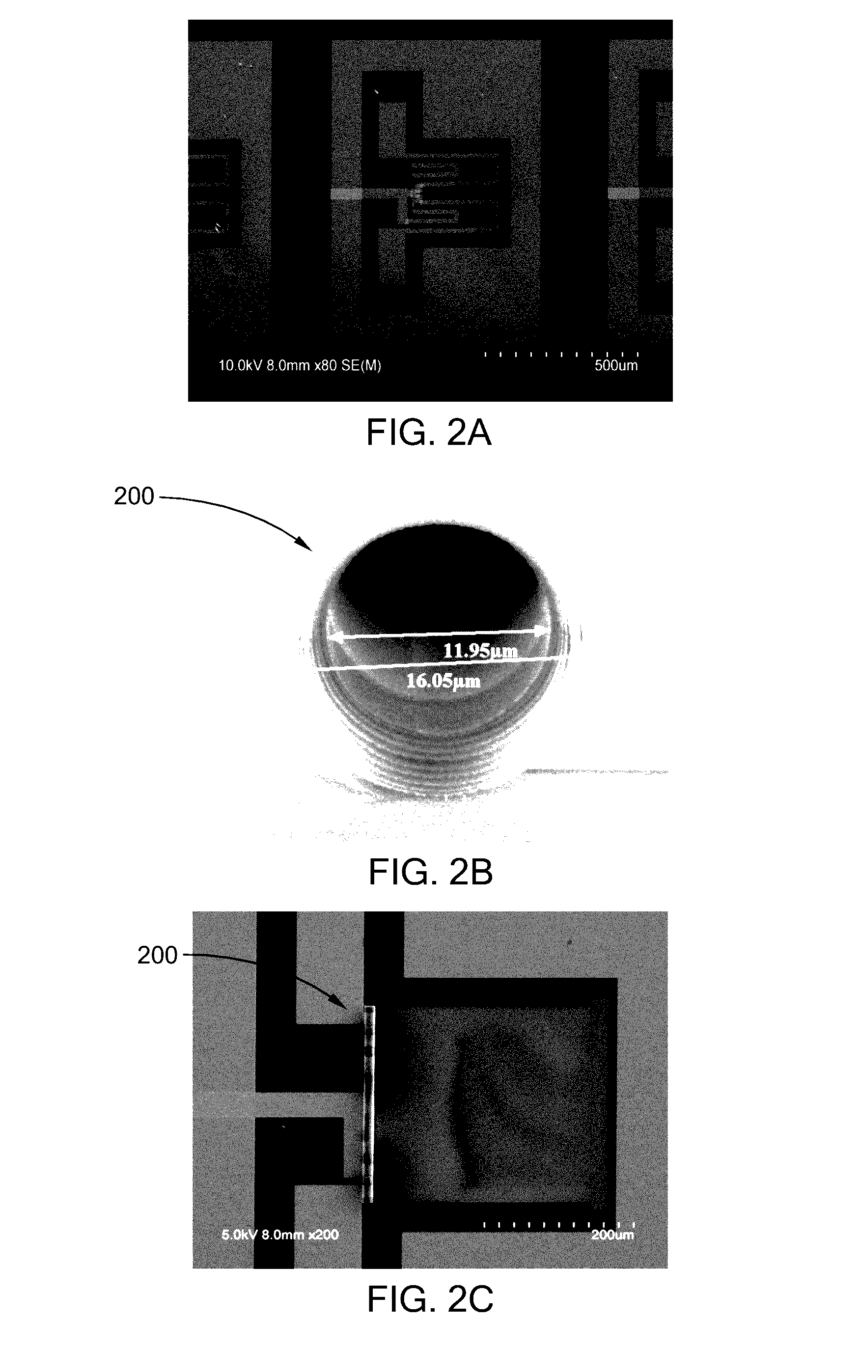
[0018]Described herein are three-dimensional (3D) tubular resonant filters formed in a self-rolling process that may have a greatly reduced on-chip footprint and significant performance improvement in RFICs. The tubular resonant filters combine the advantages of lumped element and distributed filters and have a strong immunity to substrate effects due to their extremely small footprint and minimized parasitic couplings. The rolled-up resonant filters can realize all-frequency-band design on any substrate up to 80 GHz. Prior to rolling up, the tubular resonant filters have a carefully designed multilayer planar structure that includes patterned conductive and insulating layers on a strained layer. After rolling up, the filters include rolled-up inductors and capacitors with different terminations, depending on the planar design. Low pass, high pass, and band pass tubular filters with high electrical performance can thus be created using self-rolled-up membrane (S-RUM) technology.

[001...


PUM


Abstract

A tubular resonant filter comprises a multilayer sheet in a rolled configuration comprising multiple turns about a longitudinal axis, where the multilayer sheet includes a strain-relieved layer, a patterned first conductive layer on the strain-relieved layer, an insulating layer on the patterned first conductive layer, and a patterned second conductive layer on the insulating layer and the patterned first conductive layer. The patterned first and second conductive layers and the insulating layer are interrelated to form a rolled-up inductor connected to a rolled-up capacitor on the strain-relieved layer.

Description

RELATED APPLICATIONS[0001]The present patent document claims the benefit of priority under 35 U.S.C. §119(e) to U.S. Provisional Patent Application Ser. No. 62 / 144,516, filed on Apr. 8, 2015, which is hereby incorporated by reference in its entirety.FEDERALLY SPONSORED RESEARCH OR DEVELOPMENT[0002]This invention was made with government support under award number ECCS-1309375 from the National Science Foundation. The government has certain rights in the invention.TECHNICAL FIELD[0003]The present disclosure is directed generally to filters for radiofrequency integrated circuits (RFICs), and more particularly to filters fabricated using self-rolled-up membrane (S-RUM) technology.BACKGROUND[0004]Filters are essential RFIC components for selecting a target frequency spectrum and suppressing spectral components at image frequencies. Although filters have been researched for decades, state-of-the-art technologies have serious shortcomings that have proven difficult to overcome. For exampl...

Claims


Application Information

Patent Timeline
Patent Type & Authority Applications(United States)
IPC IPC(8): H03H7/01H03H3/00H03H1/00
CPCH03H7/0115H03H1/00H03H2001/005H03H2001/0085H03H2001/0042H03H3/00
Inventor LI, XIULINGLI, MOYANGHUANG, WEN
Owner THE BOARD OF TRUSTEES OF THE UNIV OF ILLINOIS
Learn More