Engine control device

Active Publication Date: 2016-10-13
TOYOTA JIDOSHA KK
View PDF1 Cites 3 Cited by
  • Summary
  • Abstract
  • Description
  • Claims
  • Application Information

AI Technical Summary

Benefits of technology

The present patent describes an engine control device that can regulate the flow of exhaust gases in a vehicle engine to improve fuel efficiency and control emissions. The device can detect the vehicle speed and start controlling the regulator when the vehicle speed reaches a certain level. This prevents excessive draining of the vehicle parking space and helps keep the area clean. Additionally, the device can detect the position of the shift lever and start controlling the regulator when the vehicle is in reverse. This reduces the impact on the rear tires and improves overall performance. Overall, this device can improve the performance and efficiency of the engine while reducing emissions and improving safety.

Problems solved by technology

When conditions to stop the EV drive mode are met, the engine noise is increased by increasing the number of engine revolutions, and the driver is prompted to perform a switching operation between the engine drive mode and the hybrid drive mode.
However, in vehicles including an engine, when the previous travelling duration was short and the external temperature is below freezing point, and so on, there is a possibility that condensed water remaining inside an exhaust pipe freezes.

Method used


Image

  • Engine control device
  • Engine control device
  • Engine control device

Examples


Embodiment Construction

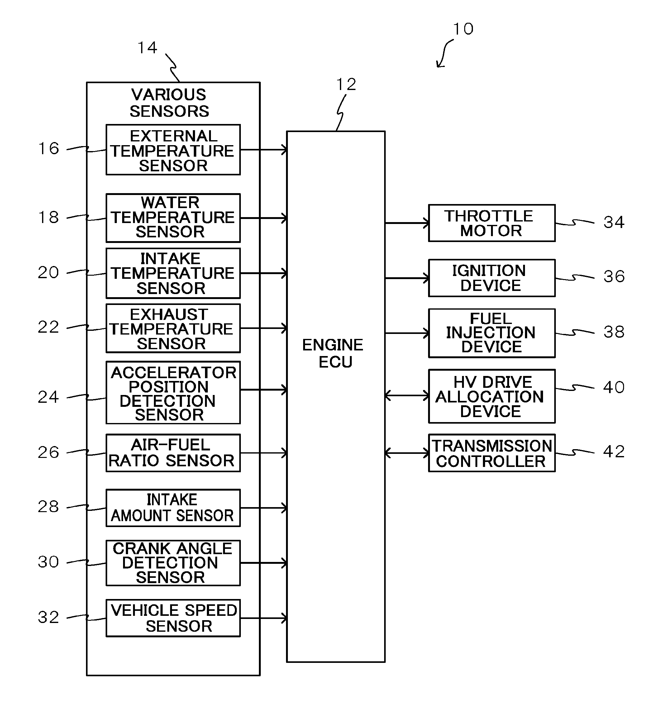
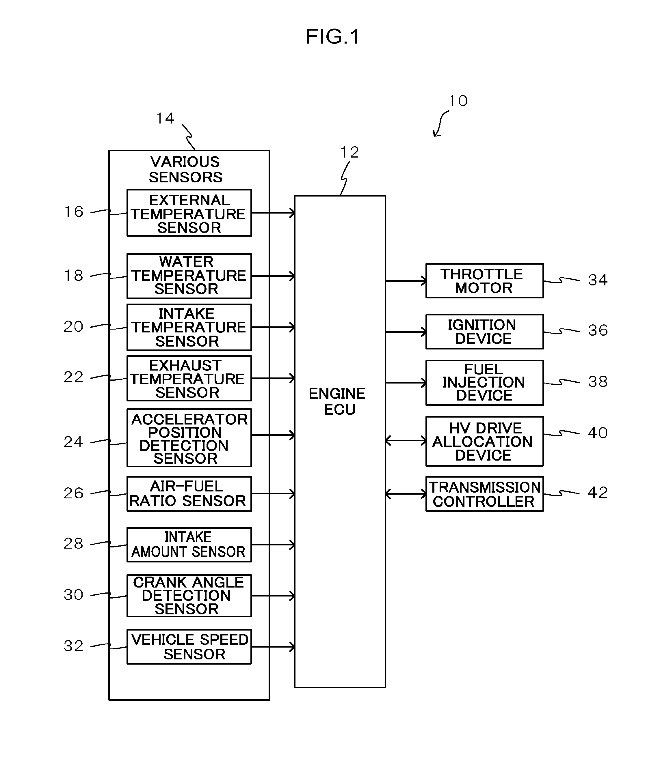
[0025]Detailed explanation follows regarding an example of an exemplary embodiment, with reference to the drawings. FIG. 1 is a block diagram illustrating a schematic configuration of an engine control device according to the present exemplary embodiment. Note that an engine control device installed in a hybrid vehicle including an engine and a motor as drive sources for travelling is explained below as an example of the engine control device.

[0026]An engine control device 10 according to the present exemplary embodiment includes an engine Electronic Control Unit (ECU) 12 serving as a controller that controls operation of the engine. The engine ECU 12 is configured by a microcomputer including a Central Processing Unit (CPU), Read Only Memory (ROM), Random Access Memory (RAM), and the like.

[0027]Various sensors 14 for controlling operation of the engine are connected to the engine ECU 12, and operation of the engine is controlled based on detection results of the various sensors 14....


PUM


Abstract

There is provided an engine control device including (1) a regulator that regulates a flow rate per unit of time of exhaust gas discharged from an engine, and (2) a controller that, in cases in which an external temperature detection section detects an external temperature below freezing point, and a previous engine operation duration is shorter than a predetermined first duration, controls the regulator such that the flow rate rises to exceed a predetermined normal state, until a predetermined second duration has elapsed since the engine was started up.

Description

CROSS-REFERENCE TO RELATED APPLICATION[0001]This application claims priority under 35 USC 119 from Japanese Patent application, No. 2015-080119 filed on Apr. 9, 2015, the disclosure of which is incorporated by reference herein.BACKGROUND[0002]1. Technical Field[0003]The present disclosure relates to an engine control device.[0004]2. Related Art[0005]Japanese Patent Application Laid-Open (JP-A) No. 2006-161593 includes an engine drive mode employing the power of an engine, an EV drive mode employing the power of a motor or a generator, and a hybrid drive mode employing the power of both the engine and the motor or generator. When conditions to stop the EV drive mode are met, the engine noise is increased by increasing the number of engine revolutions, and the driver is prompted to perform a switching operation between the engine drive mode and the hybrid drive mode.[0006]However, in vehicles including an engine, when the previous travelling duration was short and the external tempera...

Claims


Application Information

Patent Timeline
IPC IPC(8): F02D41/02F02D41/06F02D9/02F01N3/00
CPCF02D41/0235F01N3/005F02D2009/0222F02D9/02F02D41/064B60W10/06B60W10/30B60W2710/0694B60W2710/0605B60W2510/068B60W2510/0676B60W2555/20F02D41/061F02D41/062F02D41/067F02D31/003F02D33/006F02D33/02
Inventor MURATA, TOSHIO
Owner TOYOTA JIDOSHA KK
Why Eureka
Try Eureka