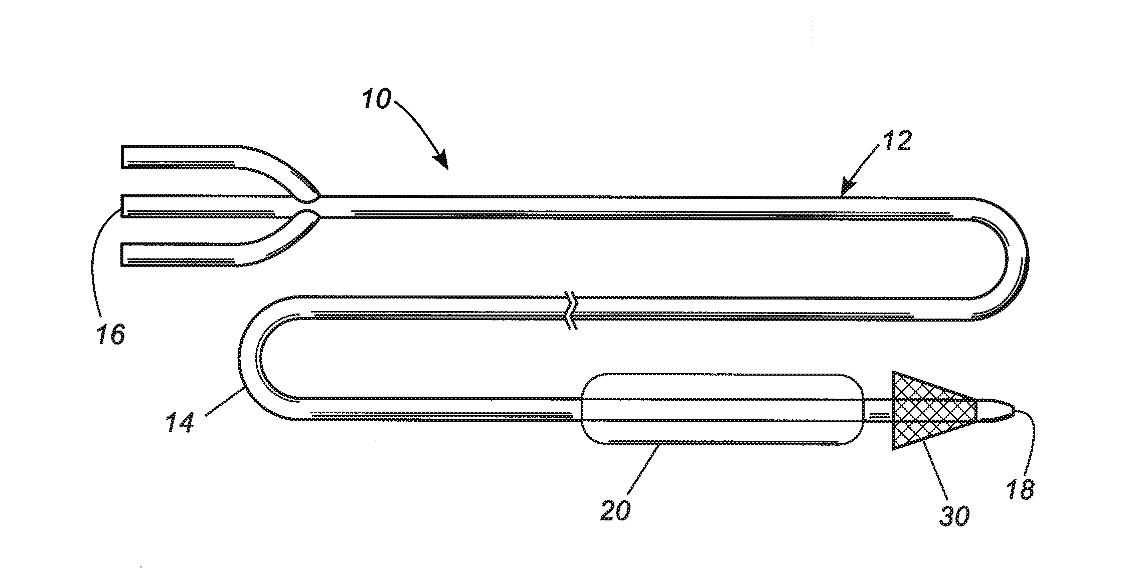
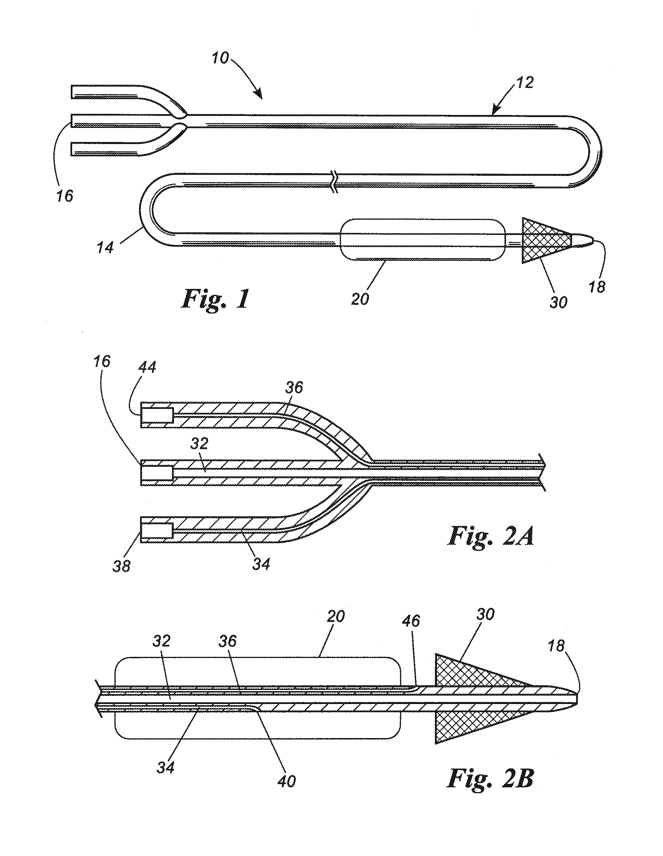
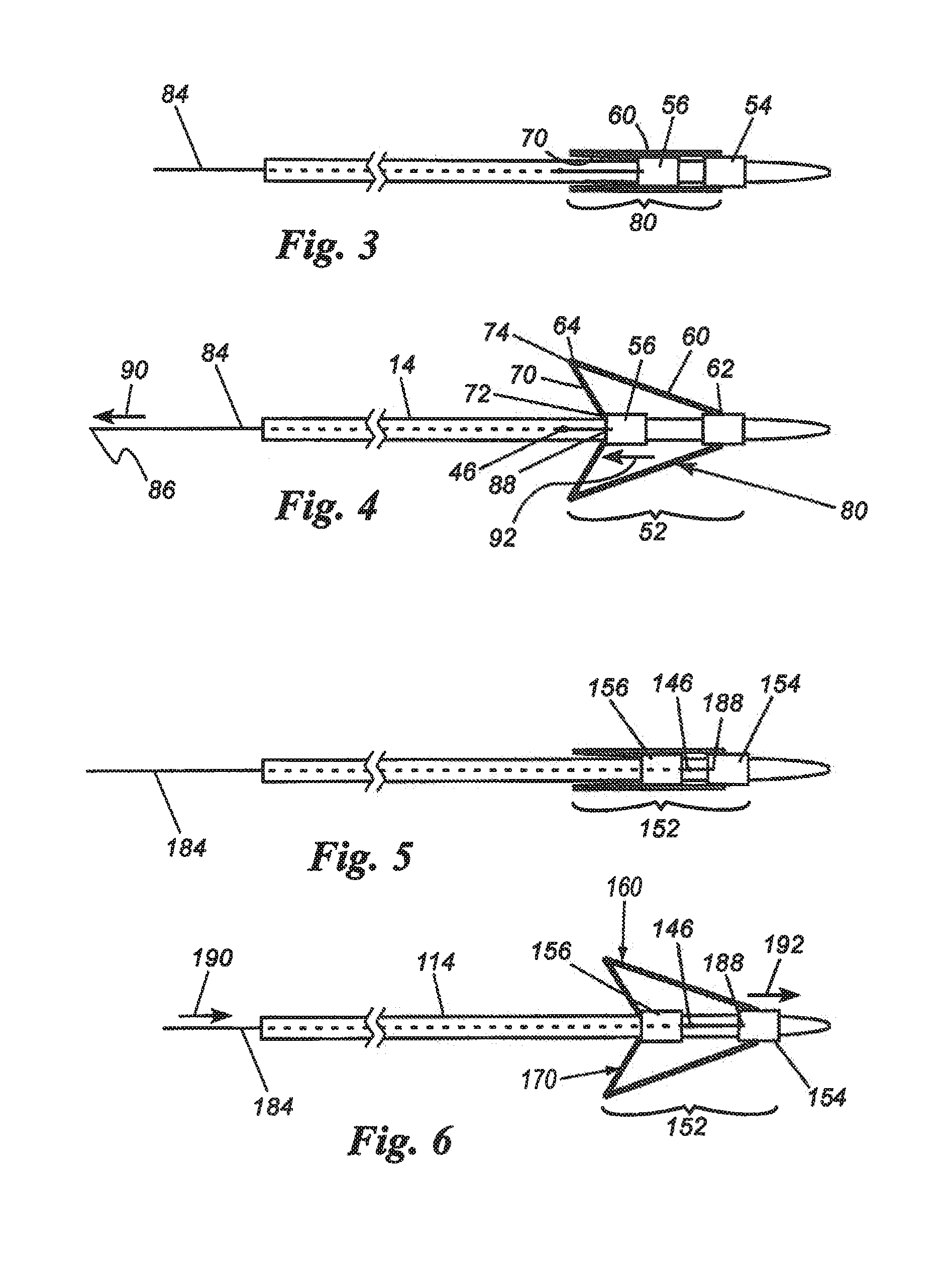
Percutaneous transluminal angioplasty device with integral embolic filter
a technology of transluminal angioplasty and filter, which is applied in the field of surgical devices, can solve the problems of adverse clinical effects, devices are prone to releasing embolic particles, and adverse clinical symptoms up to and including fatalities
- Summary
- Abstract
- Description
- Claims
- Application Information
AI Technical Summary
Benefits of technology
Problems solved by technology
Method used
Image

Examples
Embodiment Construction
[0034]The present invention can be understood more readily by reference to the following detailed description, examples, drawing, and claims, and their previous and following description. However, before the present devices, systems, and / or methods are disclosed and described, it is to be understood that this invention is not limited to the specific devices, systems, and / or methods disclosed unless otherwise specified, as such can, of course, vary. It is also to be understood that the terminology used herein is for the purpose of describing particular aspects only and is not intended to be limiting.
[0035]The following description of the invention provided as an enabling teaching of the invention in its best, currently known aspect. To this end, those skilled in the relevant art will recognize and appreciate that many changes can be made to the various aspects of the invention described herein, while still obtaining the beneficial results described herein. It will also be apparent th...
PUM
 Abstract
Description
Claims
Application Information
 - R&D
- Intellectual Property
- Life Sciences
- Materials
- Tech Scout
- Unparalleled Data Quality
- Higher Quality Content
- 60% Fewer Hallucinations
Browse by: Latest US Patents, China's latest patents, Technical Efficacy Thesaurus, Application Domain, Technology Topic, Popular Technical Reports.
© 2025 PatSnap. All rights reserved.Legal|Privacy policy|Modern Slavery Act Transparency Statement|Sitemap|About US| Contact US: help@patsnap.com