
Optical Transmission Apparatus, Method, and Applications Thereof

a transmission apparatus and optical transmission technology, applied in the field of optical communication apparatus and methods, can solve the problems of limiting the performance of fiber optic telecommunication systems, additional fiber nonlinearity penalties, and impairment of fiber nonlinearity at moderate input power and transmission distances

Inactive Publication Date: 2016-09-29
UNIV OF CENT FLORIDA RES FOUND INC
View PDF7 Cites 11 Cited by
  • Summary
  • Abstract
  • Description
  • Claims
  • Application Information

AI Technical Summary

Benefits of technology

This patent describes an optical apparatus for transmitting digital signals over a fiber optic link using multiple spatial modes. The apparatus includes a spatial mode multiplexer and a few mode fiber. The spatial mode multiplexer combines the inputs of multiple spatial modes and the output of the fiber. The fiber has a unique structure that allows for the transmission of different channels in a specific order. The technical effects of this invention include improved transmission of digital signals over long distances with reduced signal loss and increased bandwidth utilization. Additionally, the patent describes a method for transmitting multiple WDM signal channels using a few mode fiber.

Problems solved by technology

Unfortunately, fiber nonlinearity becomes an impairment at moderate input powers and transmission distances; for example, the input power threshold for stimulated Brillouin scattering (SBS) is on the order of a few mW and a self-phase modulation of 0.1 radian is induced for an input power of 100 mW over 1 km of standard single-mode fiber (SMF).
For wavelength-division multiplexed (WDM) switching and distribution networks for analog signals, cross-phase modulation (XPM) and four-wave mixing (FWM) result in additional fiber nonlinearity penalties.
In digital transmission, fiber nonlinearity would bring noise-like intra- and interchannel nonlinear crosstalk as well as signal distortion both in amplitude and phase.
It is well known that Kerr nonlinearity in fiber fundamentally limits the performance of fiber optic telecommunications systems.
When at least one of the four waves is in a different spatial mode, phase mismatching will be very large, leading to reduced FWM products.

Method used


Image

  • Optical Transmission Apparatus, Method, and Applications Thereof
  • Optical Transmission Apparatus, Method, and Applications Thereof
  • Optical Transmission Apparatus, Method, and Applications Thereof

Examples


Embodiment Construction

[0031]The embodied fiber optic communication apparatus and methods utilize few mode fiber (FMF) as a primary enabling component for fiber optic-based communication transmission apparatus (systems, links), associated methods, and applications thereof.

Few-Mode Analog Transmission Channel

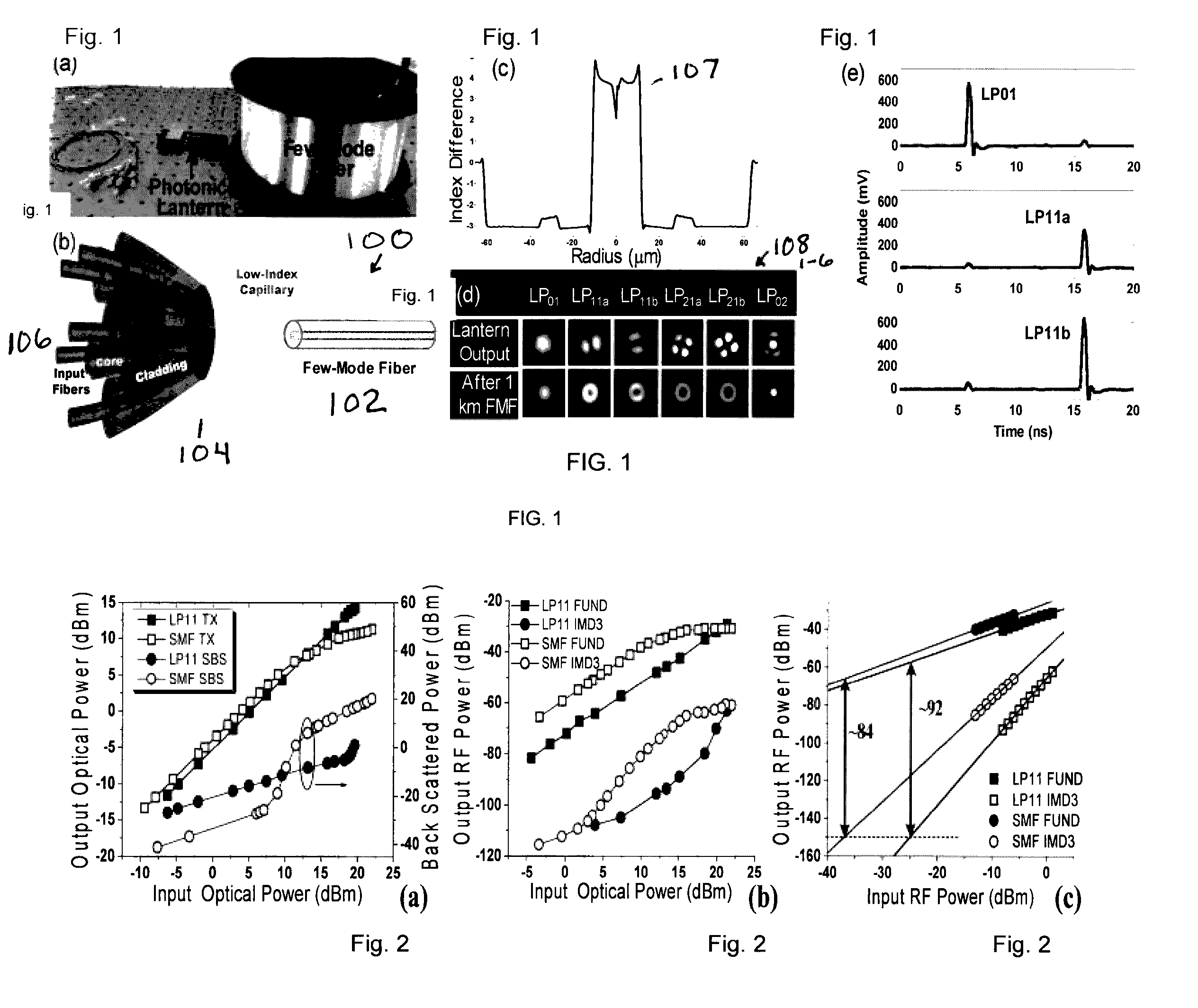
[0032]A few-mode analog transmission channel 100 includes a FMF 102 and a mode-selective photonic lantern (PL) 104, as shown in FIGS. 1(a) and (b). A 3-mode and 6-mode FMF were used in this example, both of which are of the depressed-cladding type as indicated by the profile 107 shown in FIG. 1(c). The mode-selective PL 104 converts six single-mode inputs from input single mode fibers (SMFs) 106 into the six spatial modes 1081-6 of the FMF 102 (FIG. 1(d)). The PL 104 was fabricated by inserting six input fibers into a fluorine-doped capillary with an index difference of 4E-3 and then tapering the entire structure adiabatically. The output mode intensity patterns of the PL and those at the end of a 1 km...


PUM


Abstract

Analog and digital fiber-optic telecommunication links using high-order modes in few-mode fibers (FMFs) to improve the Spurious Free Dynamic Range (SFDR) and reduce wavelength division multiplexing (WDM) penalties due to fiber nonlinearities. Methods and applications.

Description

RELATED APPLICATION DATA[0001]The instant application claims priority to US Provisional Application No. 62 / 136,848 filed on 03 / 23 / 2015 and US Provisional Application No. 62 / 167,397 filed on 05 / 28 / 2015, the subject matters of which are incorporated by reference in their entireties.GOVERNMENT FUNDING[0002]N / A.BACKGROUND[0003]Aspects and embodiments of the invention generally pertain to optical communication apparatus and methods and, more particularly to analog and digital fiber optic transmission apparatus (e.g., transmission systems, fiber optic transmission links), transmission methods, and applications thereof enabled by increased spurious free dynamic range (SFDR) and reduced wavelength division multiplexing (WDM) penalties due to fiber nonlinearities.[0004]The ability to achieve high RF gain, low noise figure and large dynamic range simultaneously determines the roles analog fiber-optic links can play in many potential commercial and military applications such as access networks...

Claims


Application Information

Patent Timeline
IPC IPC(8): H04J14/02H04J14/04H04B10/25
CPCH04J14/02H04J14/04H04B10/2504H04B10/2581G02B6/262G02B6/287H04B10/25891
Inventor LI, GUIFANGWEN, HE
Owner UNIV OF CENT FLORIDA RES FOUND INC
Learn More