
Side-Intake Piston Water Jet Propulsor

Active Publication Date: 2016-09-29
HUAN JIANCHUN JAMES C
View PDF4 Cites 1 Cited by
  • Summary
  • Abstract
  • Description
  • Claims
  • Application Information

AI Technical Summary

Benefits of technology

The invention is about a new piston water jet propulsor for marine vehicles that achieves high efficiency and negligible energy loss during water intake. The design includes an open-close valve for the side-intake of water and an inner-ring rotational valve that allows for unrestricted water intake. The technical effects include improved efficiency, simplicity, reliability, and a nearly constant efficiency over a linear thrust power.

Problems solved by technology

The kinetic energy from the rotational velocity of water doesn't contribute to the generation of thrust and therefore it is an energy waste.
This principally-embedded energy waste leads to the fact that such propulsors could hardly reach close to the ideal efficiency of propulsor.
For a given design of propeller or impeller-driven water jet, it could hardly operate in optimal pitch angle at all vehicle speeds, and that is why a propeller or an impeller-driven water jet can only reach its highest efficiency at the design point.
As the vehicle operates at off-deign points, the efficiency of such propulsors degrades greatly.
In other words, such propulsors could hardly offer the thrust power that is proportional to the input power.
In real life, that fact reflects a poor acceleration of a marine vehicle equipped with such propulsors.
Unlike the oar recovering through air, an issue relating to the efficiency of a piston water jet propulsor is the energy cost in the water intake process during the piston's recovering or back stroke.
The piston's mechanical work to overcome this resistance during the recovering stroke is an energy waste, which negatively affects the efficiency of the propulsor.

Method used


Image

  • Side-Intake Piston Water Jet Propulsor
  • Side-Intake Piston Water Jet Propulsor
  • Side-Intake Piston Water Jet Propulsor

Examples


Embodiment Construction

1. The Principle of Side-Intake

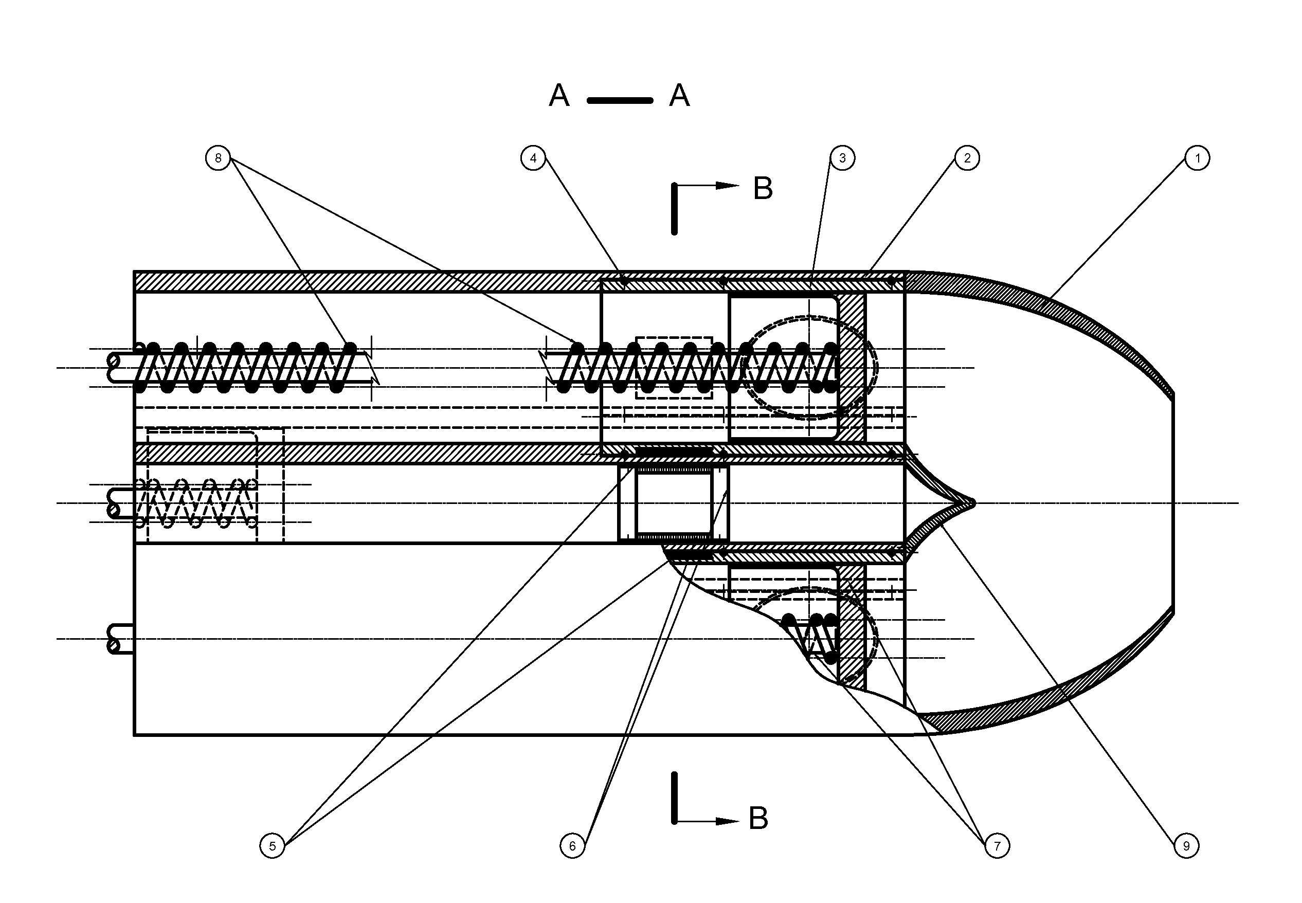
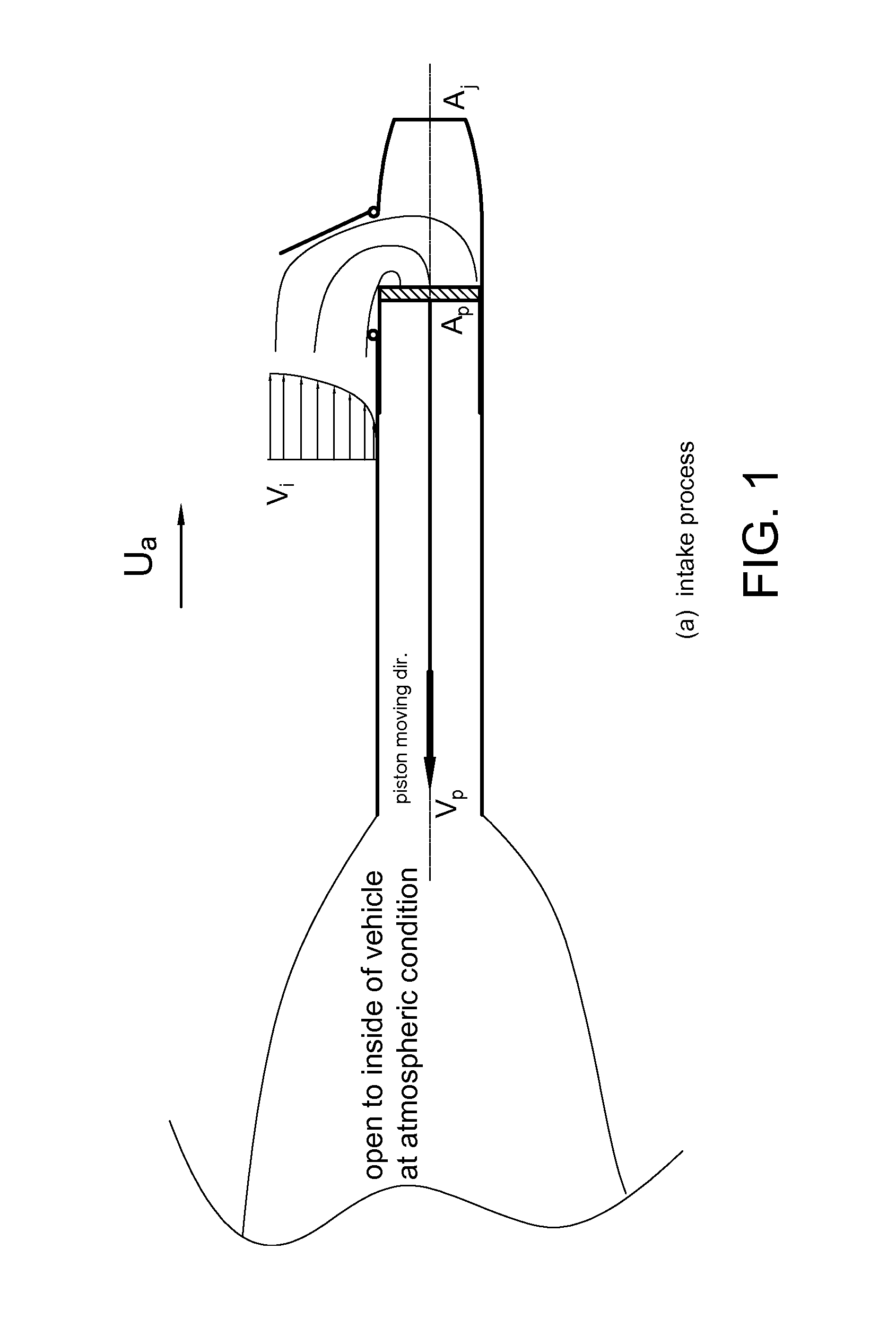
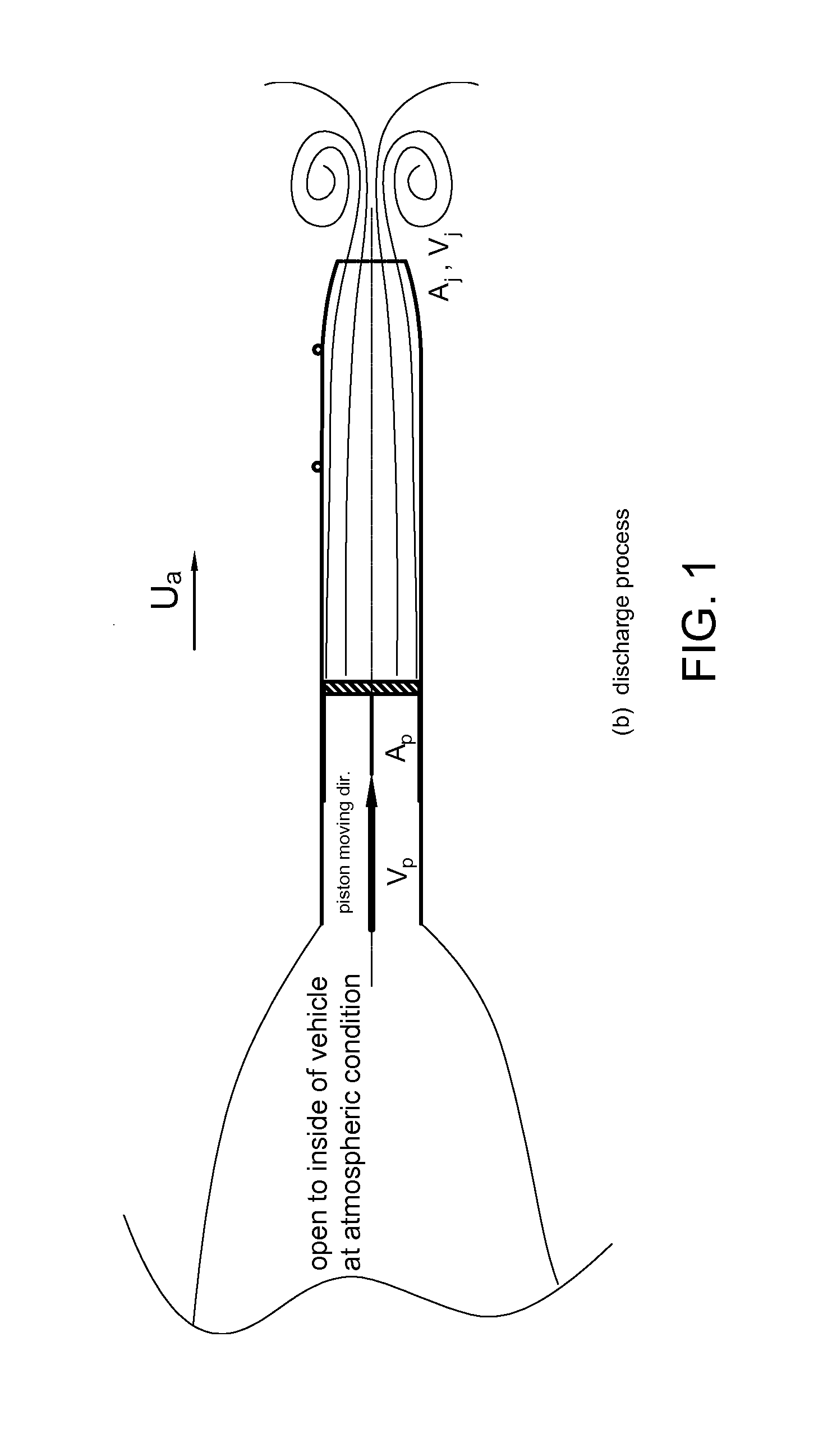
[0015]The concept of Side-Intake of water for a piston water jet propulsor can be shown in a schematic diagram in FIG. 1. First, it requires a tube for a piston to do reciprocating motion inside. The tube could be, but not limited to, a cylinder; however the inventor will refer such a tube to as a cylinder for convenience throughout. The concept of the Side-Intake opens intake holes on the side and near the discharging end of the cylinder wall. An open-close valve must be installed to open and close the Side-Intake holes during the piston's strokes for intake and discharge respectively. The discharge end is completed with a jet nozzle. With a piston installed inside the cylinder, the system becomes a one-cylinder Side-Intake Piston Water Jet Propulsor. FIG. (1)-(a) shows the water intake process. In this process, the valve is in fully open position and the piston takes the back (or recovering) stroke, namely the piston moves toward left as shown in the...


PUM


Abstract

A piston water jet propulsor for propelling marine vehicles employs the concept of the Side-Intake of water and generates thrust through piston's reciprocating motion in cylinder. The concept of the Side-Intake opens water intake holes on the side and near the discharge end of the cylinder wall with a rotational and electric-magnetic actuated valve to control the intake holes open for water intake or closed during water discharge through the nozzle at the end of the cylinder. The principle feature of the Side-Intake is the separation of the cylinder into a dry and a wet compartment at any time piston moves. The dry compartment is always at atmospheric condition, which allows the piston encounters only air resistance during its recovering stroke. The Side-Intake Piston Water Jet Propulsor requires at least a 2-cylinder system to maintain a continuous water intake and discharge. The preferred embodiment is a Side-Intake Piston Water Jet Propulsor with 4 cylinders.

Description

FIELD OF THE INVENTION[0001]Propellers, impeller-driven water jet propulsor and piston or reciprocating water jet propulsors for marine vehicles, Water pumps.BACKGROUND OF THE INVENTION[0002]For marine vehicle propulsion, propellers or impeller-driven water jets are mostly being used. The principle to generate thrust in water is to use some mechanism to build up water kinetic energy from the water velocity in line with the thrust axis. Marine propellers or marine impeller-driven water jets all depend on the spin of blades in water to build up the water kinetic energy. Because of the spin of blades in water, the kinetic energy built up in water is contributed not only from the water velocity in the thrust-producing axis but also from the water rotational velocity about the spinning axis. The kinetic energy from the rotational velocity of water doesn't contribute to the generation of thrust and therefore it is an energy waste. This principally-embedded energy waste leads to the fact t...

Claims


Application Information

Patent Timeline
IPC IPC(8): B63H11/06F04F5/54F04F5/24F04F5/46F04B1/04F04B23/10
CPCB63H11/06F04B1/0408F04B1/0421F04F5/54F04B23/106F04F5/24F04F5/46F04B1/0452F04B19/04F04B19/22B63H1/32
Inventor HUAN, JIANCHUN
Owner HUAN JIANCHUN JAMES C
Learn More