
Network printing system

Inactive Publication Date: 2001-04-17
HITACHI KOKI IMAGING SOLUTIONS
View PDF17 Cites 109 Cited by
  • Summary
  • Abstract
  • Description
  • Claims
  • Application Information

AI Technical Summary

Benefits of technology

Another object of an embodiment of the present invention to provide an efficient, simple and reliable method for communicating the network address of user workstation in a printing network to a printer in the same network.
Another object of an embodiment of the present invention is to provide an efficient and reliable system for transmitting a network address of a network printer to a user workstation.

Problems solved by technology

Unfortunately, implementation of a monitor task for retrieving the network address of the printer and then transmitting a message to a printer with the network address of the user workstation is a cumbersome procedure for establishing direct communication between a user workstation and a printer which receives print jobs originating at the user workstation.

Method used


Image

  • Network printing system
  • Network printing system
  • Network printing system

Examples


Embodiment Construction

will be made with reference to the accompanying drawings, in which:

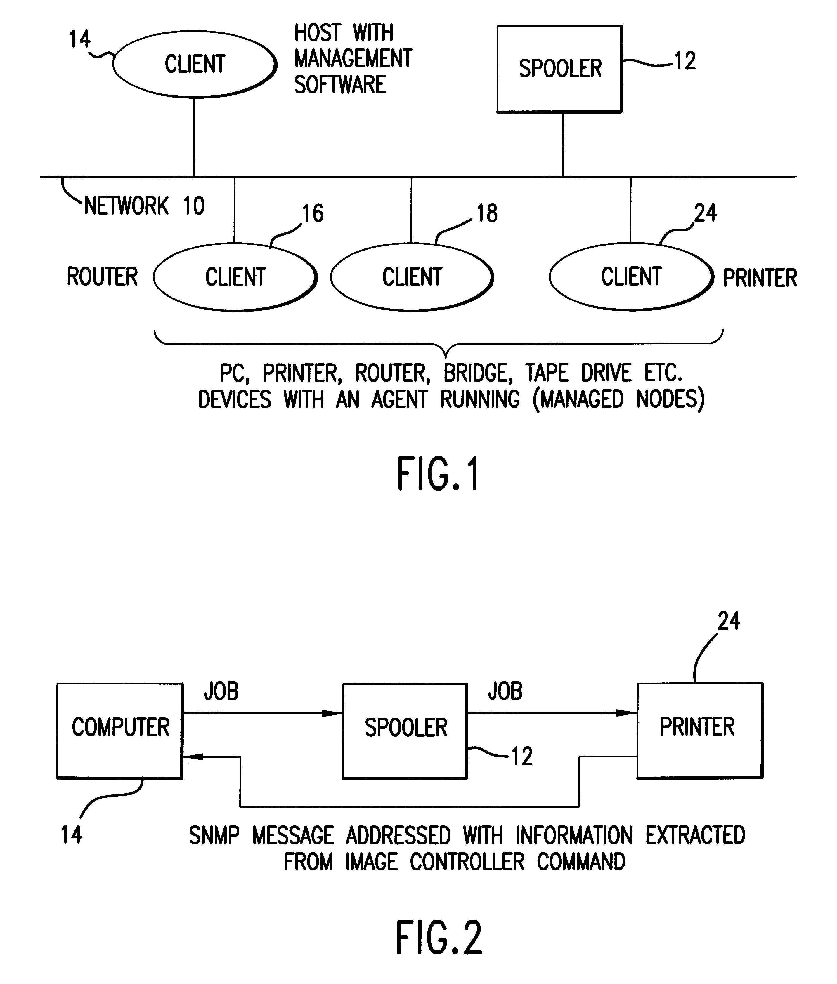
FIG. 1 is a block diagram of an electronic network which may employ method and system according to an embodiment of the present invention;

FIG. 2 is a block diagram representation of a portion of the network of FIG. 1, showing the manner in which print job requests from a sending client are routed through a spooler to a receiving client terminal such as a printer;

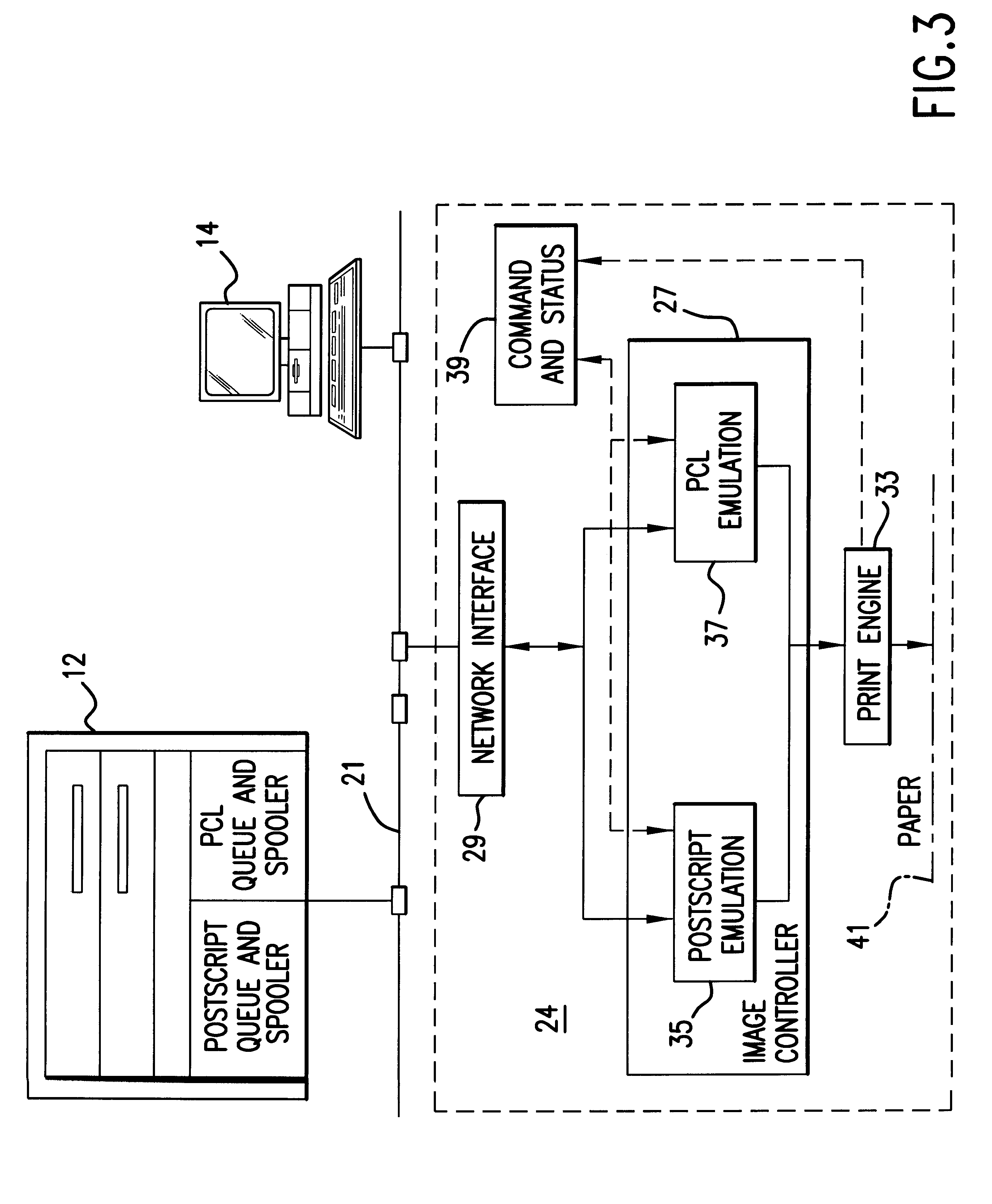
FIG. 3 illustrates processes in a printer and spooler of an embodiment of the network of FIG. 2.

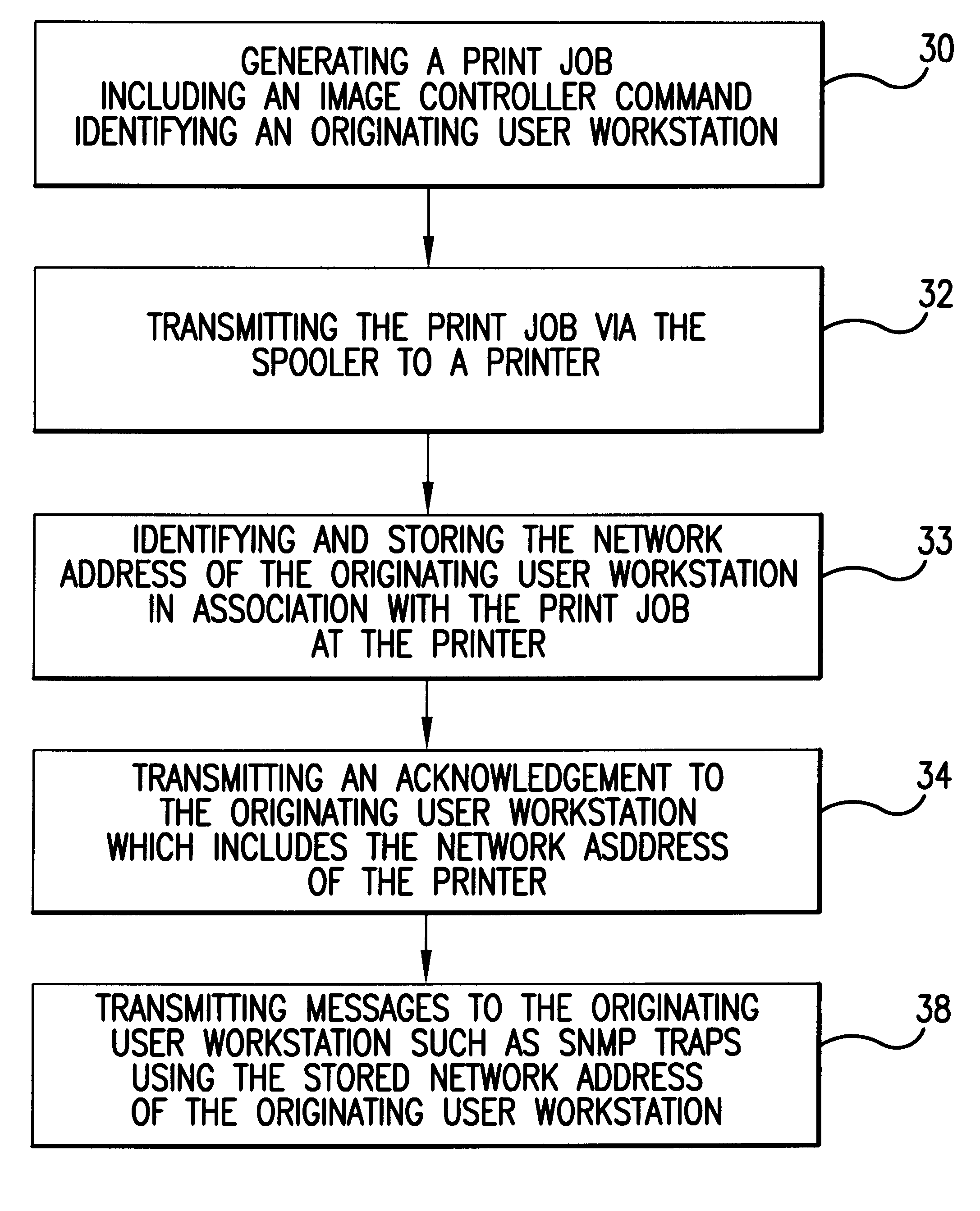
FIG. 4 is a flow diagram illustrating processes executing at a workstation and an image controller of a printer to communicate the network address of the workstation to the printer;

FIG. 5 is a block diagram illustrating the successive steps of a method of extracting the network address of a user workstation from an image controller command in accordance with an embodiment of the invention;

FIG. 6 is a representation of a print job which is generated and transmitted ...


PUM


Abstract

A printing network including at least one user workstation and a printer is described. The user workstation transmits print jobs with image controller commands having data which is representative of a network address of the user workstation. An image controller at the printer receiving the print job executes the image controller commands in the print jobs to extract the network address of the user workstation. Processes in the printer store the extracted network address of the user workstation in association with data representative of the print job. The printer transmits messages to the user workstation concerning the status of the print job using the network address extracted from the print job.

Description

1. Field of the InventionThe present invention relates to electronic networks having a plurality of client or agent terminals or systems, and more particularly to networks having one or more printers for receiving print jobs from computers or other printer users within the network.2. Related ArtWhile different types of protocols are possible for status monitoring and configuration of devices within an electronic network, one of the most commonly used protocols is the Simple Network Management Protocol (SNMP). The SNMP defines asynchronous messages or "traps" to be transmitted to a management application. In a typical electronic network, a plurality of clients in the form of computer workstations are coupled to the network together with one or more printers and an intermediate spooler. In order to receive traps from a printer, a computer workstation typically must first "register" with the printer by communicating a network address associated with the computer workstation to the prin...

Claims


Application Information

Patent Timeline
IPC IPC(8): H04L12/24G06F3/12B41J29/38
CPCH04L41/0213G06F3/1293G06F3/1207G06F3/1229G06F3/1236G06F3/1285
Inventor MANGLAPUS, LEVI LLOYD GARCIAUCHENIK, IGORSORKIN, MAXIM ARIELMURPHY, MARK PATRICKZIA, SUSANEGAN, ALISTAIR MICHAEL
Owner HITACHI KOKI IMAGING SOLUTIONS
Learn More