
Electric machine

a technology of electric motors and windings, which is applied in the direction of dynamo-electric machines, electrical equipment, magnetic circuit shapes/forms/construction, etc., can solve the problems of increasing the risk of arcing and the ageing of the insulation of stator windings, and achieve the effect of reducing the magnetic flux

Active Publication Date: 2020-10-20
BOMBARDIER TRANSPORTATION GMBH
View PDF9 Cites 1 Cited by
  • Summary
  • Abstract
  • Description
  • Claims
  • Application Information

AI Technical Summary

Benefits of technology

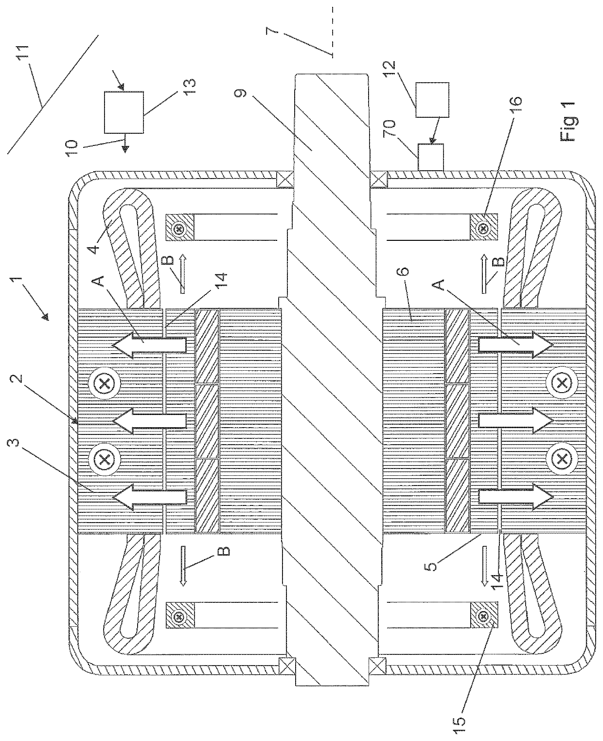
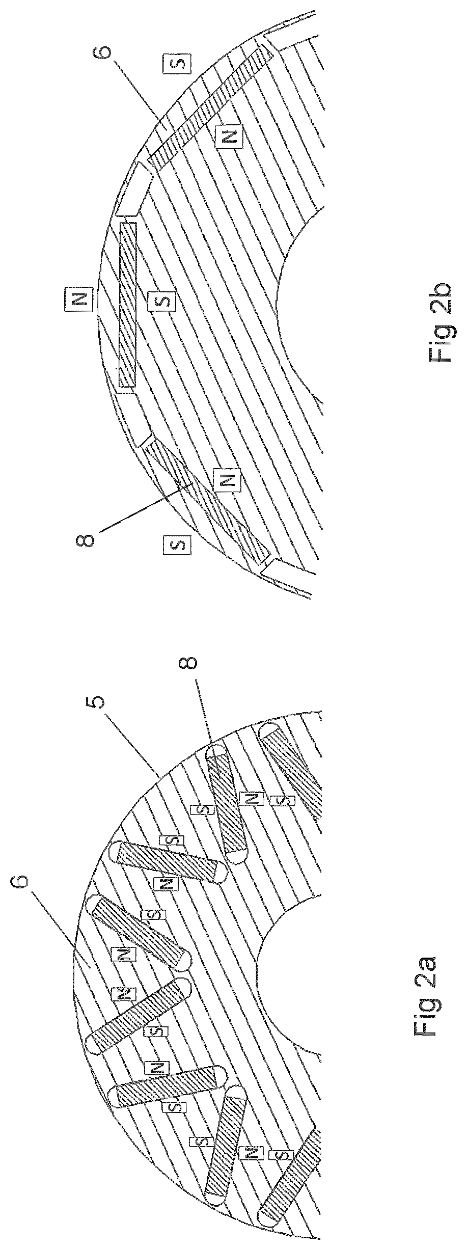
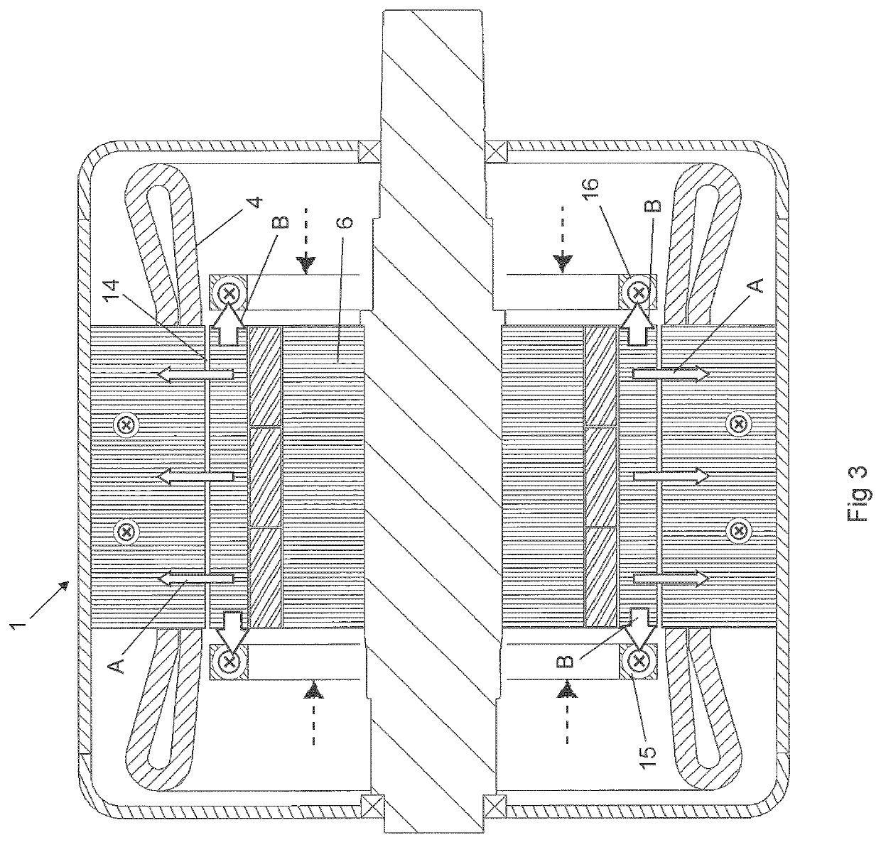
[0011]A reduction of the magnetic flux from the permanent magnets through the air gap is in the electric machine according to the invention obtained by providing the machine with said at least one member or an agent of a material having a high magnetic permeability configured to be positioned with respect to the rotor body so as to reduce the magnetic flux from the permanent magnets through the air gap. This means that magnetic flux from the permanent magnets will thanks to said at least member or agent to a lower degree cross said air gap between the rotor body and the stator body than in absence of such a member or agent. The disadvantages of a high magnetic flux from the permanent magnets through said air gap mentioned above may by this be avoided. Furthermore, said at least one member is configured to reduce the magnetic flux from the permanent magnets through said air gap by diverting a part of the magnetic flux otherwise led from the permanent magnets through said air gap to instead be led through this member. To position a said member of a material having a high magnetic permeability to divert a part of magnetic flux from the permanent magnets constitutes an efficient, simple and reliable way of obtaining a substantial reduction of said magnetic flux through the air gap when desired. Additionally, said member is moveable with respect to the rotor body between at least two different positions in which the member is configured to divert differently large proportions of said magnetic flux from the permanent magnets therethrough. This movability makes it possible to have a high magnetic flux from the permanent magnets through the air gap when this is really favourable and still be able to reduce this magnetic flux when a high magnetic flux is undesired and / or harmful. The electric machine comprises means configured to move said at least one member between said different positions with respect to the rotor body, which provides for an easy adaption of the magnetic flux from the permanent magnets through said air gap to the operating conditions of the electric machine prevailing. Finally, said means is configured to move said at least one member to a position with respect to the rotor body with a maximum reduction of magnetic flux through said air gap upon creation of arcing or a short-circuit in said stator winding or any cables or equipment connected to said stator winding. The negative consequences of arcing mentioned above may by this be efficiently addressed.
[0018]According to another embodiment of the invention the electric machine comprises a control unit configured to control said means to move said at least one member during operation of the electric machine for changing the proportion of said magnetic flux from the permanent magnets led through said air gap. The arrangement of such a control unit makes it possible to easily adjust the magnetic flux from the permanent magnets through said air gap to the operating conditions prevailing for the electric machine.
[0023]According to another embodiment of the invention the electric machine comprises a said ring at one axial end or both axial ends of the rotor body radially close to said air gap. Rings at these locations will reduce the magnetic flux from the permanent magnets through said air gap by diverting a part thereof to go through said ring (s) instead, and the size of this part may easily be modified by moving the ring axially with respect to a rotation axis of the rotor, which is the subject of another embodiment of the invention.
[0025]According to another embodiment of the invention the rotor body and the stator body are arranged to have said air gap directed axially therebetween with respect to a rotation axis of the rotor and said at least one member is arranged close to said air gap. Thus, this electric machine is a so-called axial magnetic flux machine. According to an embodiment constituting further development of this embodiment the rotor body has an annular part and a said ring is arranged along and within said annular part of the rotor body and / or along and outside said annular part of the rotor body. Such a ring or rings with such a location may efficiently divert a part of the magnetic flux from the permanent magnets of the rotor to go through said ring instead of through said air gap.
[0028]According to another embodiment of the invention directed to the arcing problem the machine comprises a said agent comprising a ferromagnetic powder stored in a container inside a casing enclosing the stator and the rotor and configured to be released upon occurrence of arcing to reach the region of said air gap for reducing magnetic flux through the air gap by bridging magnetic poles of the permanent magnets of the rotor. This constitutes an efficient way of rapidly stop arcing when occurring. The electric machine may then be restored to a normal condition by dismounting and cleaning while minimizing destruction of components thereof through said arcing.

Problems solved by technology

A high magnetic flux through said air gap from the permanent magnets will result in a high no-load voltage at maximum speed resulting in ageing of the insulation of the stator winding and increasing the risk for arcing.
Such arcing is a potential show-stopper for a permanent magnet motor due to remaining risk and / or the impact of competitiveness of layout and design requirements.

Method used


Image

  • Electric machine
  • Electric machine
  • Electric machine

Examples


first embodiment

[0050]FIG. 1 shows schematically the main parts of an electric machine 1 according to the invention. This electric machine has a stator 2 having a stator body 3 with a stator winding 4 wound therearound and configured to electrically create a plurality of stator poles disposed around the inner periphery of the stator body. The stator winding is received in radial slots in the stator body extending over the entire length of this body. The total number of slots and number of slots per pole may be any conceivable, but as an example these numbers may be 48 and 4.

[0051]The electric machine further comprises a rotor 5 (see also FIGS. 2a and 2b) with a rotor body 6, which could be made of a solid high permeability material or could be, as the stator body, made of a laminated assembly of mutually electrically insulated angular plates of magnetic steel axially stacked with respect to an axis of rotation 7 of the rotor for keeping eddy current losses in these bodies at low levels and the roto...

second embodiment

[0057]FIGS. 5-8 illustrates schematically an electric machine according the invention in the form of a so-called single sided axial magnetic flux machine having the rotor body 20 and the stator body 21 arranged to have said air gap 22 directed axially therebetween with respect to the rotation axis 23 of the rotor. The rotor body has here an annular part 24, and a said ring 25, 26 of a material with a high magnetic permeability is arranged along and within said annular part 24 and along and outside this annular part of the rotor body. It is shown in FIGS. 5 and 6 through the arrows A how magnetic flux from the permanent magnets in the rotor is led through said air gap and is comparatively high, since the rings 25, 26 are in a position in which they are not able to divert any noticeable part of the magnetic flux from the permanent magnets therethrough. However, the rings 25, 26 are movable axially with respect to the rotation axis of the rotor with respect to the rotor body towards an...

third embodiment

[0058]FIG. 9 illustrates schematically an electric machine according to the invention having a similar design as that shown in FIGS. 5-8 with the difference that this electric machine is a double sided axial flux permanent magnet machine instead of a single sided such. The rings 35, 36 are here shown in a position corresponding to that in FIG. 7 of diverting a considerable proportion of the magnetic flux from the permanent magnets to go through these rings instead of through the air gaps 32.


PUM


Abstract

An electric machine (1) has a stator (2) with a stator body (3) and a stator winding (4) and a rotor (5) rotatably disposed with respect to the stator and having a rotor body (6) with a plurality of permanent magnets received therein. The rotor is disposed with an air gap (14) between the rotor body and the stator body and to make a magnetic flux to pass between the permanent magnets of the rotor body and stator poles of the stator body through this air gap. The machine further comprises at least one member (15, 16) or an agent of a material having a high magnetic permeability configured to be positioned with respect to the stator body (6) so as to reduce the magnetic flux (A) from the permanent magnets through said air gap.

Description

TECHNICAL FIELD OF THE INVENTION AND BACKGROUND ART[0001]The present invention relates to an electric machine comprising:[0002]a stator having a stator body with a stator winding wound therearound and configured to electrically create a plurality of stator poles disposed around the periphery of the stator body,[0003]means configured to connect the stator winding to an AC source or receiver, and[0004]a rotor rotatably disposed with respect to the stator and having a rotor body with a plurality of permanent magnets received therein,[0005]said rotor being disposed with an air gap between the rotor body and the stator body and to make a magnetic flux to pass between the permanent magnets of the rotor body and the stator poles of the stator body through said air gap so as to apply a driving torque to the rotor in motor operation of the electric machine and feeding electric power to the stator winding in generator operation of the electric machine.[0006]Such an electric machine may operat...

Claims


Application Information

Patent Timeline
Patent Type & Authority Patents(United States)
IPC IPC(8): H02K11/27H02K21/02H02K1/12
CPCH02K21/028H02K11/27H02K1/12H02K2213/06
Inventor ANDERSSON, SVANTESANDBERG, ÅSA
Owner BOMBARDIER TRANSPORTATION GMBH
Learn More