
Power apparatus

Active Publication Date: 2016-09-22
PEGATRON
View PDF0 Cites 1 Cited by
  • Summary
  • Abstract
  • Description
  • Claims
  • Application Information

AI Technical Summary

Benefits of technology

The power apparatus described in this patent has a power coordinating unit that helps to supply stable power to the internal load. When the control unit is in a protective mode, the power coordinating unit takes over and provides the current needed for stable operation. In the operational mode, the apparatus uses an auxiliary voltage to supply power to the internal load, while the coordinating current is cut off to prevent any impact on the control unit. This design allows for a seamless transition between the protective and operational modes, ensuring a smooth and safe operation of the power apparatus.

Problems solved by technology

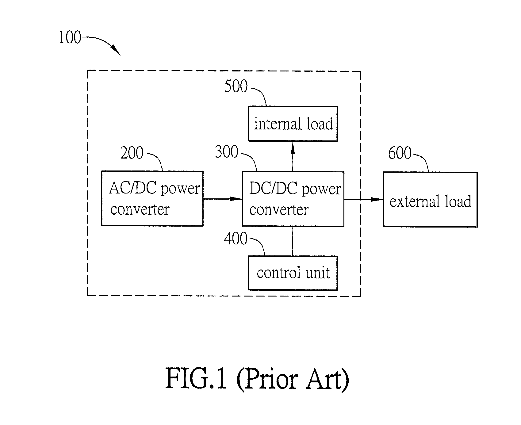
However, when the control unit 400 operates in a protective mode, the control unit 400 can not control the power conversion of the DC / DC power converter 300.
If the internal load 500 is a power consuming circuit, it may not get enough power to regularly operate.

Method used


Image

  • Power apparatus
  • Power apparatus
  • Power apparatus

Examples


first embodiment

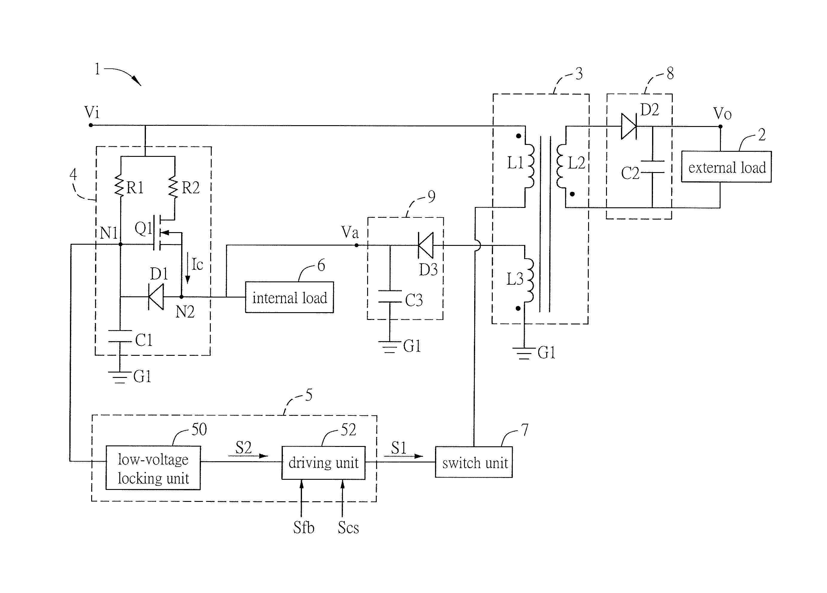
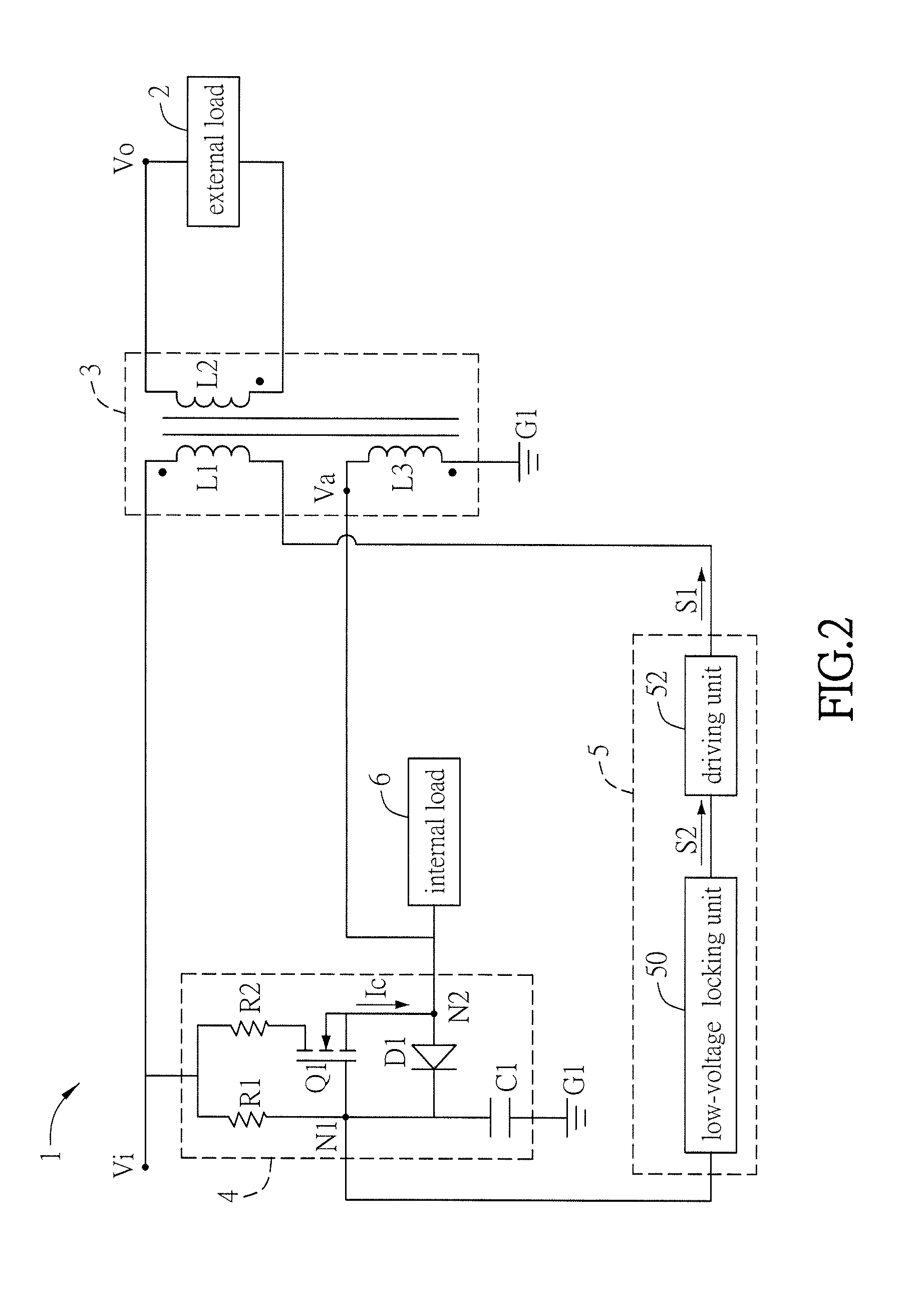
[0029]Referring to FIG. 2, FIG. 2 is a schematic diagram showing the power apparatus according to the The power apparatus 1 is adapted for an external load 2. The power apparatus 1 comprises the transformer 3, the power coordinating unit 4, the control unit 5 and the internal load 6.

[0030]In the first embodiment, the transformer 3 transforms the input voltage Vi into the output voltage Vo and the auxiliary voltage Va in response to an operating signal S1. The transformer 3 comprises the first coil L1, the second coil L2 and the auxiliary coil L3 electromagnetically coupled to one another. The first coil L1 is configured to receive the input voltage Vi, the second coil L2 is configured to provide the output voltage Vo to the external load 2, and the auxiliary coil L3 is configured to provide the auxiliary voltage Va. The input voltage Vi may be a DC voltage which originates from the AC voltage (mains electricity) rectified by the bridge rectifier (not shown in the figure) of the pow...

second embodiment

[0045]Referring to FIG. 5, FIG. 5 is a schematic diagram showing the power apparatus according to the The equal or similar elements in FIG. 5 and FIG. 1 are labeled with the same reference symbols. The power apparatus 1 may be for example but not limited to a flyback power supply, a forward power supply or other type power supply.

[0046]Referring to FIG. 5, in the second embodiment, the power apparatus 1 may further comprise the switch unit 7, the first output unit 8 and the second output unit 9. The switch unit 7 is coupled between the driving unit 52 and the first coil L1. The driving unit 52 selectively transmits the operating signal S1 to the switch unit 7. The switch unit 7 may be for example but not limited to a MOSFET (Metal-Oxide-Semiconductor Field-Effect Transistor), a BJT (Bipolar Junction Transistor) or an IGBT (insulated-gate bipolar transistor).

[0047]The first output unit 8 is coupled between the second coil L2 and the external load 2. The first output unit 8 can be co...


PUM


Abstract

A power apparatus for an external load comprises a transformer, a power coordinating unit, a control unit and an internal load. The transformer is adapted for transforming an input voltage into an output voltage and an auxiliary voltage in response to an operating signal. The transformer comprises a first coil, a second coil and an auxiliary coil electromagnetically coupled to one another. The power coordinating unit comprises a first resistor, a transistor, a second resistor, a diode and a capacitor. The control unit is coupled between the first node and the first coil and configured to selectively generate the operating signal. When the control unit operates in a protective mode, the control unit is configured not to generate the operating signal, the power coordinating unit is configured to generate a coordinating current supplied to the internal load by using a starting voltage of the first node.

Description

CROSS REFERENCE TO RELATED APPLICATIONS[0001]This Non-provisional application claims priority under 35 U.S.C. §119(a) on Patent Application No(s). 104108821 filed in Taiwan, Republic of China on Mar. 19, 2015, the entire contents of which are hereby incorporated by reference.BACKGROUND[0002]1. Technical Field[0003]The disclosure relates to a power apparatus, in particular to a power apparatus with power coordination.[0004]2. Related Art[0005]Nowadays, various electronic devices e.g. copiers, printers, audio and video products, desktop computers and mobile computers are popular daily devices. These electronic devices obtain power through power supply which is a necessary component to supply stable and adequate power to a single or various electronic devices.[0006]Power supply can convert AC input e.g. mains electricity into DC required by electronic device. Referring to FIG. 1, the conventional power apparatus 100 usually comprise the AC / DC power converter 200, the DC / DC power conver...

Claims


Application Information

Patent Timeline
IPC IPC(8): H02M3/335
CPCH02M2001/0009H02M3/33507H02M1/36H02M3/33523H02M1/0006H02M3/33561
Inventor FAN CHIANG, CHAO-TUNGJHOU, JHENG-TINGHU, MING-LIN
Owner PEGATRON
Learn More