
Method for operating an electric arc furnace, and electric arc furnace

a technology of electric arc furnace and electric arc furnace, which is applied in the direction of furnace control devices, electric heating for furnaces, lighting and heating apparatus, etc., can solve the problems of electrode breakage, fragments falling off, and electrode consumption in ambient air, and achieve the effect of cooling particularly effectively

Inactive Publication Date: 2016-09-22
PRIMETALS TECH GERMANY
View PDF5 Cites 2 Cited by
  • Summary
  • Abstract
  • Description
  • Claims
  • Application Information

AI Technical Summary

Benefits of technology

The patent describes a method for controlling the temperature of an electrode in an arc furnace to reduce mechanical stresses and improve efficiency. The method involves introducing a first additive into the electrode to produce an endothermic chemical reaction, which requires energy and cools the electrode. The amount and flow rate of the first additive can be controlled to adjust the reaction's position. Additionally, a second additive can be introduced to influence the field strength of the arc, reducing or increasing its energy. This helps to control the arc's operating phases and improve the overall performance of the arc furnace.

Problems solved by technology

At the top of the electrodes, the electrode temperature is of the order of the ambient or shop temperature, whereas at the bottom of the electrodes just above the molten bath is at approximately 3000 K. These high temperatures acting together with the arc result in increased electrode consumption in the ambient air.
Temperature gradients along the electrodes can also result in mechanical stresses which can cause fragments to flake off or, in extreme cases, electrode breakage.
Electrode breakage would not only result in increased electrode consumption but also in production downtimes and carbon pick-up in the steel if the graphite electrode or fragments thereof fall into the molten bath.
Increasing the conductivity in the arc, i.e. in the plasma, results in larger electrode gaps and therefore a reduction in the current fluctuations and so-called flicker.
At the same time the radiated power is increased in magnitude and volume, so that the large-volume radiation of energy results in a rapid scrap heating process.
On the other hand, reducing the conductivity of the plasma results in a small electrode gap and lower radiated powers and therefore also in lower radiation losses on the furnace walls.
In the case of the conventional electric arc furnace for melting scrap material, such a method has so far not been used.
However, as the trickling-down water evaporates, the lower section of the electrode is not cooled.
Moreover, the interior of the electrode receives no cooling at all.

Method used


Image

  • Method for operating an electric arc furnace, and electric arc furnace
  • Method for operating an electric arc furnace, and electric arc furnace
  • Method for operating an electric arc furnace, and electric arc furnace

Examples


Embodiment Construction

[0035]The examples described in greater detail below constitute preferred embodiments of the present invention.

[0036]FIG. 1 shows a sectional side view of an arc furnace 10 according to the prior art. The arc furnace 10 is implemented as an electric arc furnace. The furnace 10 comprises an upper shell section 12 and a lower shell section 14 which can be moved relative to one another. The arc furnace 10 is used for melting a charge material 16, in particular scrap steel. The charge material 16 is placed in the lower shell section 14.

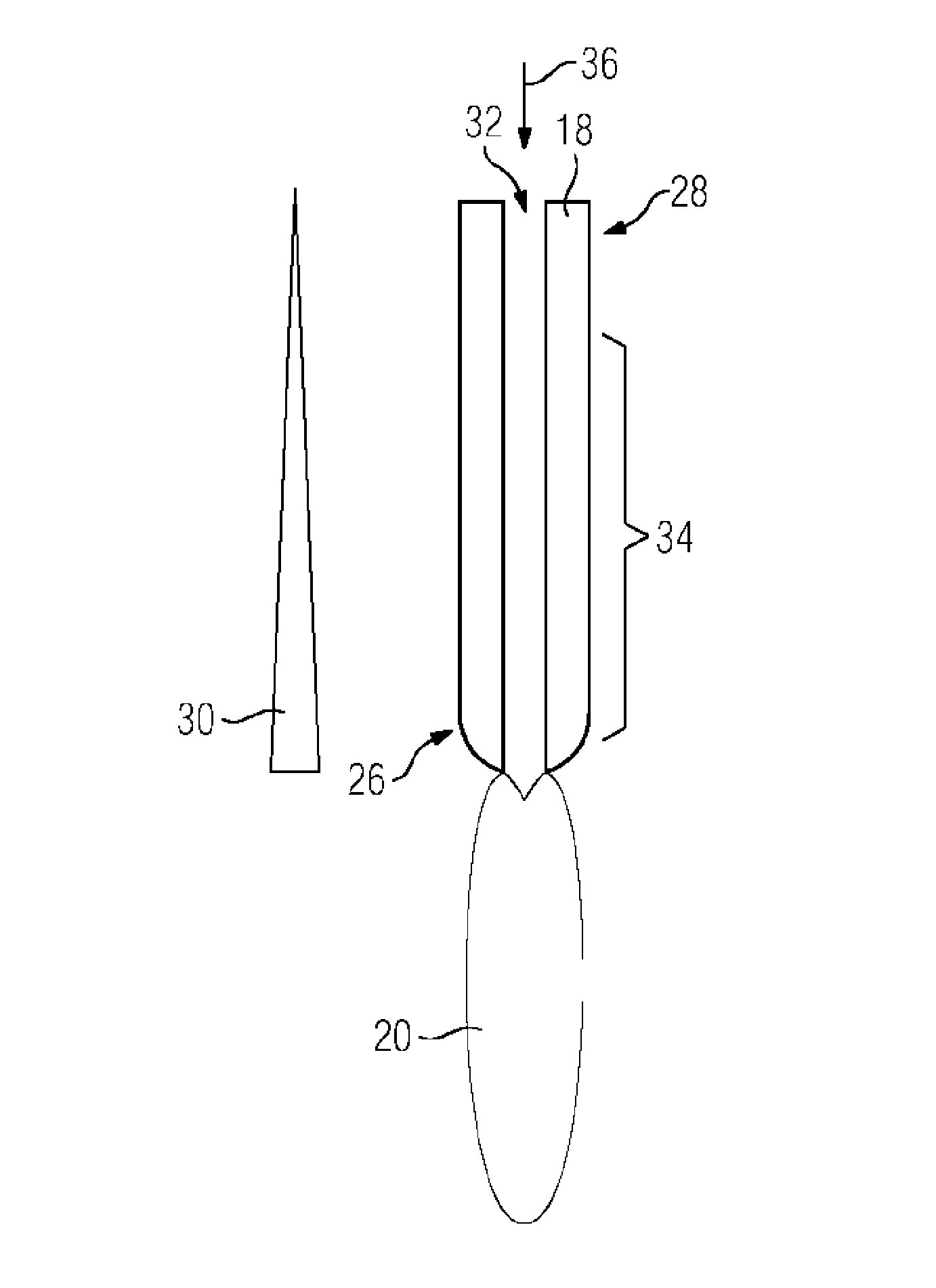
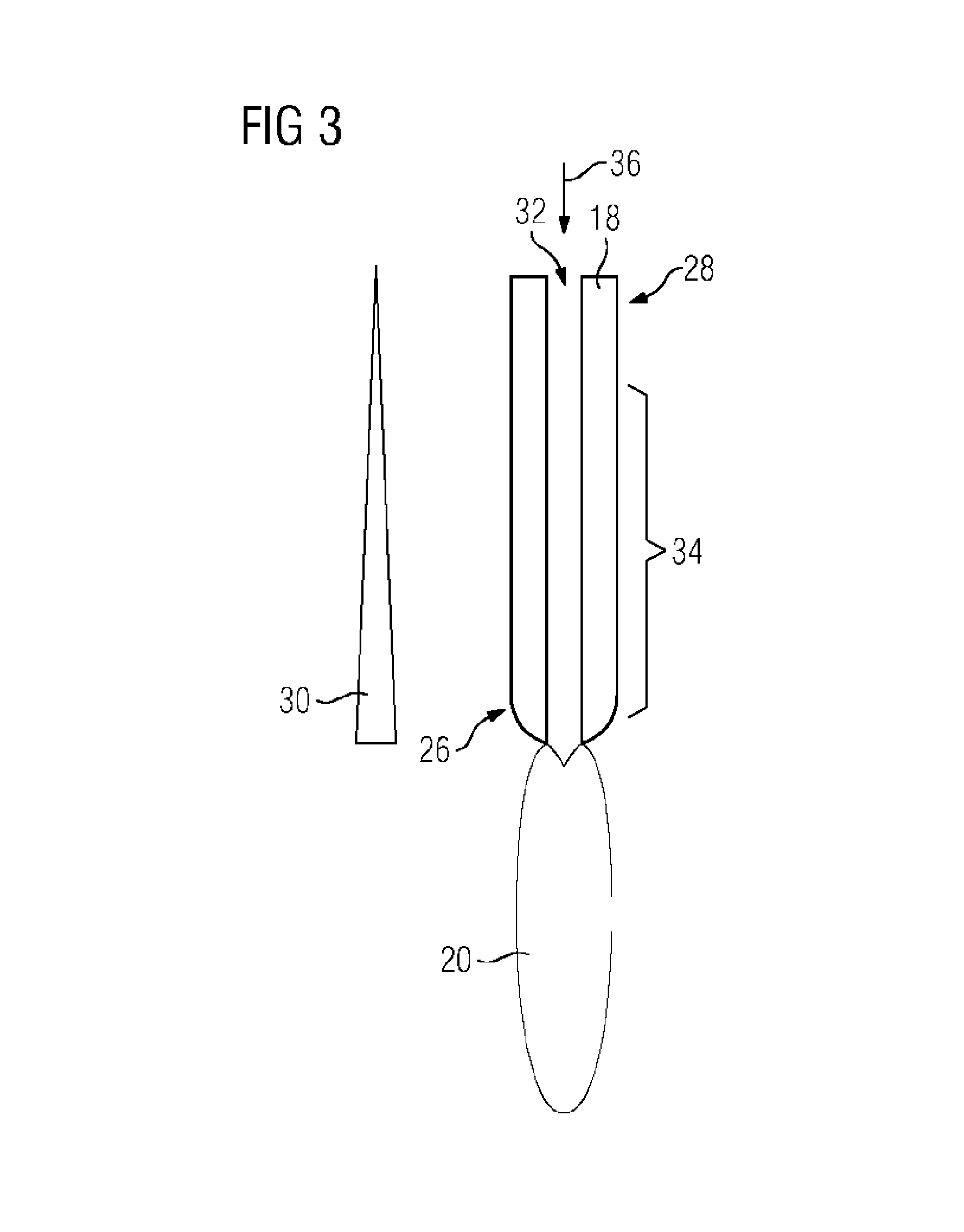
[0037]The arc furnace 10 additionally comprises at least one electrode 18. In this exemplary embodiment, the arc furnace 10 comprises three electrodes 18. The electrodes 18 are connected to a furnace transformer (not shown here) by which a voltage can be provided at the electrodes 18. At the electrodes 18, the voltage and / or the current intensity are selected such that an arc 20 is produced between the electrodes 18 and the charge material 16 to be melted...


PUM

PropertyMeasurementUnit
Timeaaaaaaaaaa
Flow rateaaaaaaaaaa
Strengthaaaaaaaaaa

Abstract

A method for operating an electric arc furnace (10) which has at least one electrode (18) having a through-opening (32). An electric arc (20) is generated between the at least one electrode (18) and a material to be melted (16). A first additive is introduced into the through-opening (32) of the electrode (18) for causing an endothermic chemical reaction which is controlled such that the chemical reaction is caused in a predetermined region (34) of the at least one electrode (18), wherein the region faces the material to be melted (16).

Description

CROSS-REFERENCE TO RELATED APPLICATIONS[0001]The present application is a 35 U.S.C. §§371 national phase conversion of PCT / EP2014 / 072751, filed Oct. 23, 2014, which claims priority of German Patent Application No. 102013222158.4, filed Oct. 31, 2013, the contents of which are incorporated by reference herein. The PCT International Application was published in the German language.TECHNICAL FIELD[0002]The present invention relates to a method for operating an electric arc furnace. The present invention additionally relates to an electric arc furnace for melting a charge material.TECHNICAL BACKGROUND[0003]In an arc furnace, in particular an electric arc furnace, an electric arc supplies electrical energy in the form of arc discharges to solid scrap metal and, in a subsequent phase, the arc supplies electrical energy to a molten bath via graphite electrodes. In the first phase, the solid scrap is heated and melted directly by the arc and / or indirectly by the radiation of the arc. In sub...

Claims


Application Information

Patent Timeline
IPC IPC(8): C21C5/52C21C7/072H05B7/18H05B7/06F27D11/10F27B14/06
CPCC21C5/5217F27D11/10F27B14/06F27D2019/0068H05B7/06C21C7/072H05B7/185F27D19/00Y02P10/20
Inventor BALDAUF, MANFREDHERGT, MARTINMATSCHULLAT, THOMAS
Owner PRIMETALS TECH GERMANY
Learn More