
Ball tee

a ball tee and ball technology, applied in the field of ball tees, can solve the problems of poor simulation of hitting a pitched ball, concussion shock through the bat and the ball tee, and the prior art ball tees present several drawbacks, so as to reduce the tipping effect, improve the effect of shape, and reduce the effect of weigh

Active Publication Date: 2016-09-22
MAXOVER LLC
View PDF1 Cites 1 Cited by
  • Summary
  • Abstract
  • Description
  • Claims
  • Application Information

AI Technical Summary

Benefits of technology

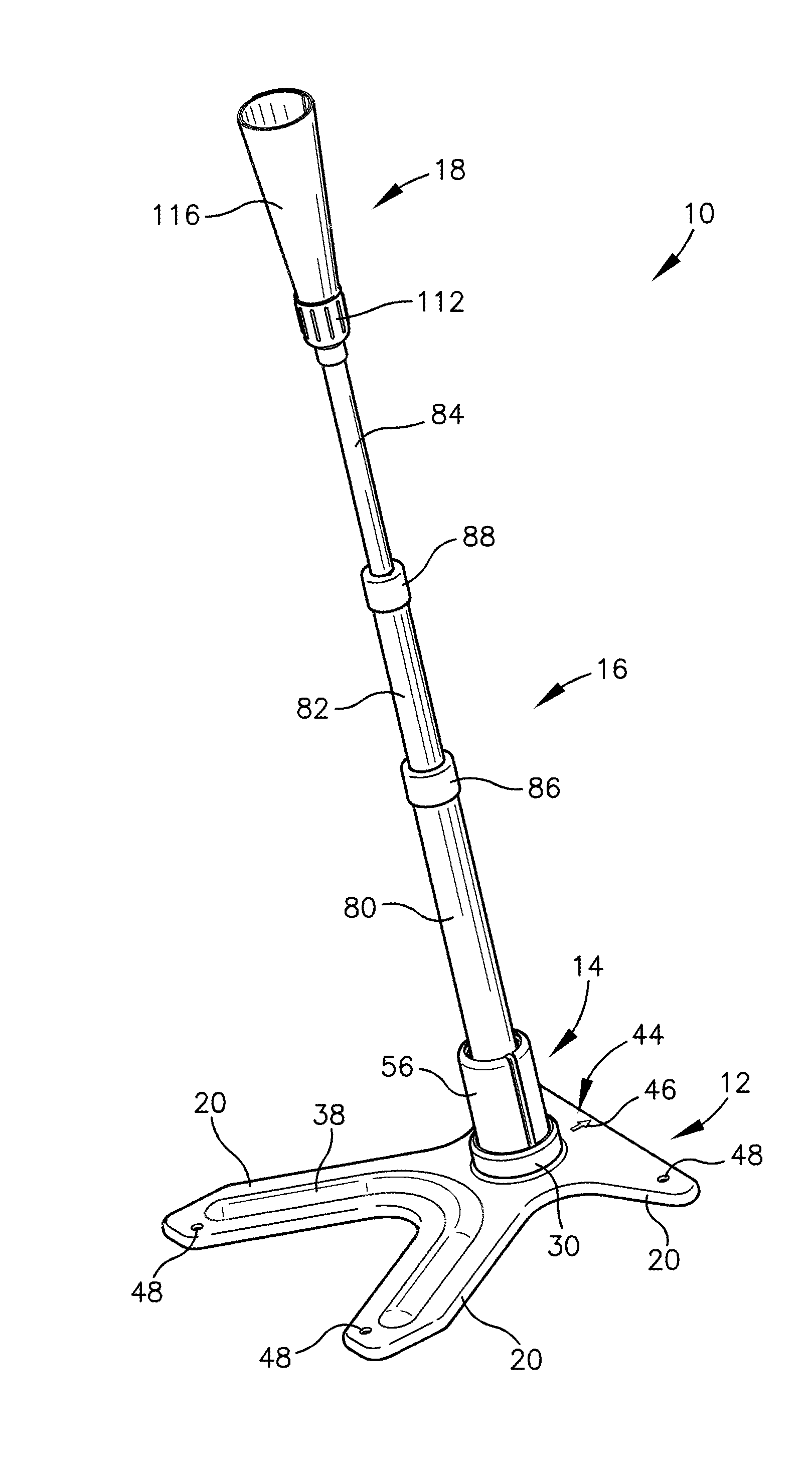
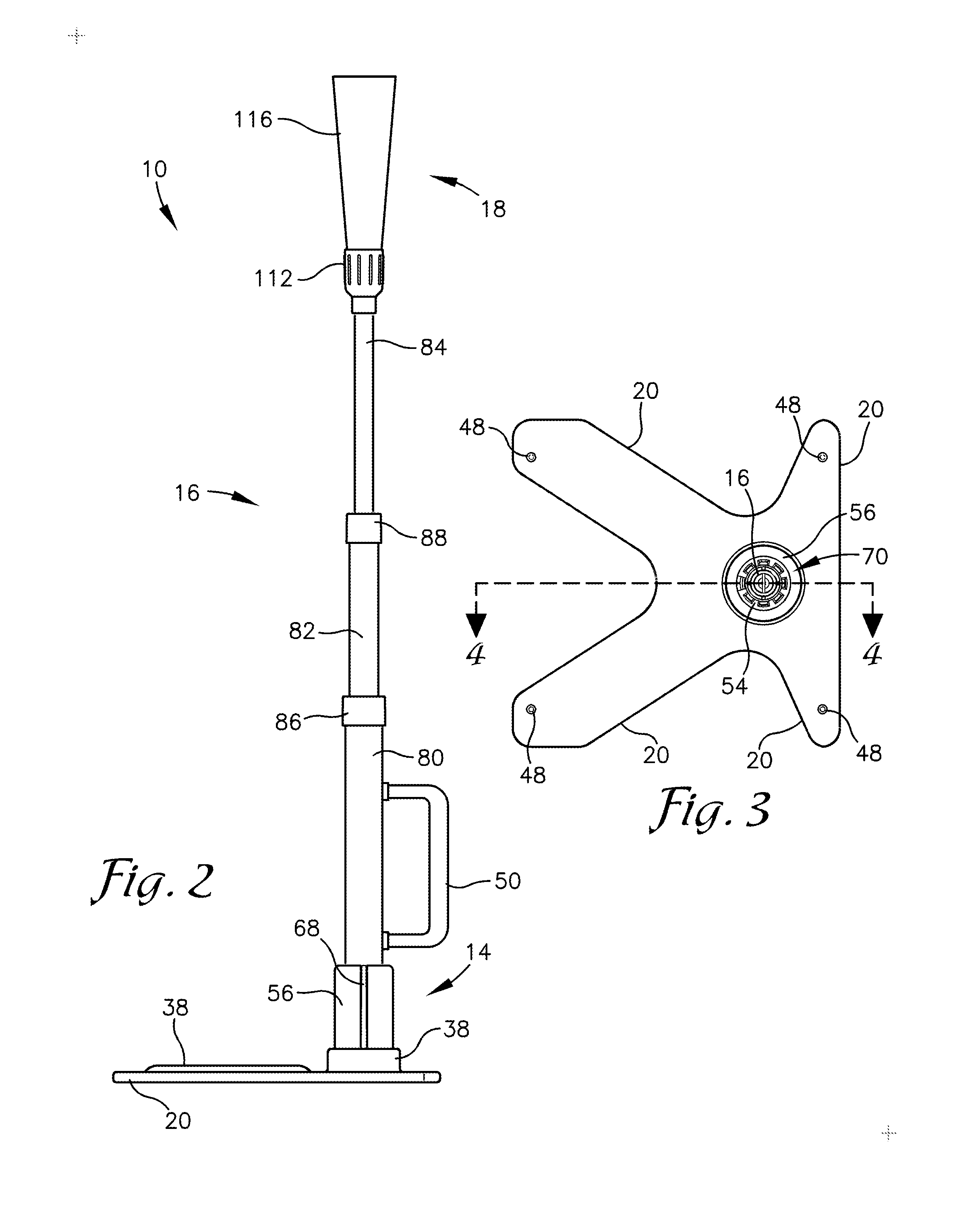
[0007]Embodiments of the invention solve the above-mentioned problems and provide a distinct advance in the art by providing an improved ball tee. The ball tee includes a ball holder formed of a rolled sheet for gently holding the ball until the hit. The ball tee also includes an improved base for reduced tipping based upon a more efficient shape and the option to add additional weight. The ball tee is also more resistant to damage due to an improved clamp for holding a post to the base and a lack of adhesives in the ball holder. Finally, the ball tee has a wide range of motion making it appropriate for batters of all sizes.

Problems solved by technology

However, ball tees of the prior art present several drawbacks.
First, the ball tees provide excessive resistance to the batter, which is a poor simulation for hitting a pitched ball.
Ball tees of the prior art have a tendency to grip the ball too tightly, which leads to a concussive shock through the bat and through the ball tee.
Second, the ball tees have a tendency to slide or tip over following a hit.
Third, ball tees have a tendency to break and wear under the repeated pressure of being hit.
Fourth, ball tees have a limited range of heights.
The slides which provide friction within the telescoping posts also have a tendency to wear out.

Method used


Image

  • Ball tee
  • Ball tee
  • Ball tee

Examples


Embodiment Construction

[0033]The following detailed description of the invention references the accompanying drawings that illustrate specific embodiments in which the invention can be practiced. The embodiments are intended to describe aspects of the invention in sufficient detail to enable those skilled in the art to practice the invention. Other embodiments can be utilized and changes can be made without departing from the scope of the invention. The following detailed description is, therefore, not to be taken in a limiting sense. The scope of the invention is defined only by the appended claims, along with the full scope of equivalents to which such claims are entitled.

[0034]In this description, references to “one embodiment”, “an embodiment”, “embodiments”, “various embodiments”, “certain embodiments”, “some embodiments”, or “other embodiments” mean that the feature or features being referred to are included in at least one embodiment of the technology. Separate references to “one embodiment”, “an e...


PUM


Abstract

The invention is directed to a ball tee for supporting a ball. The ball tee includes a base, a telescoping post, a clamp, and a ball holder. The base presents a plurality of laterally extending arms and an opening. The telescoping post includes a static segment and a first telescoping segment. The clamp is configured to secure the telescoping post to the base. The clamp is disposed at least partially within said opening of the base and at least partially around said static segment of the telescoping post. The ball holder is disposed atop the telescoping post configured to support a ball. The ball holder includes a rolled flexible sheet and an outer holder (and in some embodiments an inner holder). The rolled flexible sheet presents a generally conical shape oriented with a large end upward for supporting the ball, and is at least partially disposed within the outer holder.

Description

RELATED APPLICATIONS[0001]This non-provisional patent application is a continuation, and claims priority benefit to all common subject matter of U.S. patent application Ser. No. 14 / 862,813, filed Sep. 23, 2015, and entitled “BALL TEE,” which is now U.S. Pat. No. 9,358,440 that issued on Jun. 7, 2016 (“the '440 patent”). The '440 patent claims priority benefit, with regard to all common subject matter, of earlier-filed U.S. Provisional Patent Application No. 62 / 125,156, filed on Jan. 14, 2015, and entitled “BASEBALL BATTING TEE” (“the '156 application). The '440 patent and the '156 application are each hereby incorporated by reference in their entirety into the present application.BACKGROUND[0002]1. Field[0003]Embodiments of the invention relate to baseball equipment. More specifically, embodiments of the invention relate to ball tees for holding a ball for a batter.[0004]2. Related Art[0005]Baseball players, softball players, coaches, and the like rely on ball tees to play their gam...

Claims


Application Information

Patent Timeline
Patent Type & Authority Applications(United States)
IPC IPC(8): A63B69/00
CPCA63B69/0002A63B2208/0204A63B2069/0008A63B69/0075A63B2225/093
Inventor BURRELL, JONATHAN C.
Owner MAXOVER LLC
Learn More