Receiver unit and receiving method
a receiver unit and receiver technology, applied in the field of receiver units, can solve problems such as system instability, incomplete circularity of received signals, and problems such as problems such as problems such as errors, and achieve the effects of avoiding error propagation due to the iterative process, accurate receiving of symbols, and improving iterative symbol detection
- Summary
- Abstract
- Description
- Claims
- Application Information
AI Technical Summary
Benefits of technology
Problems solved by technology
Method used
Image
Examples
embodiment 1
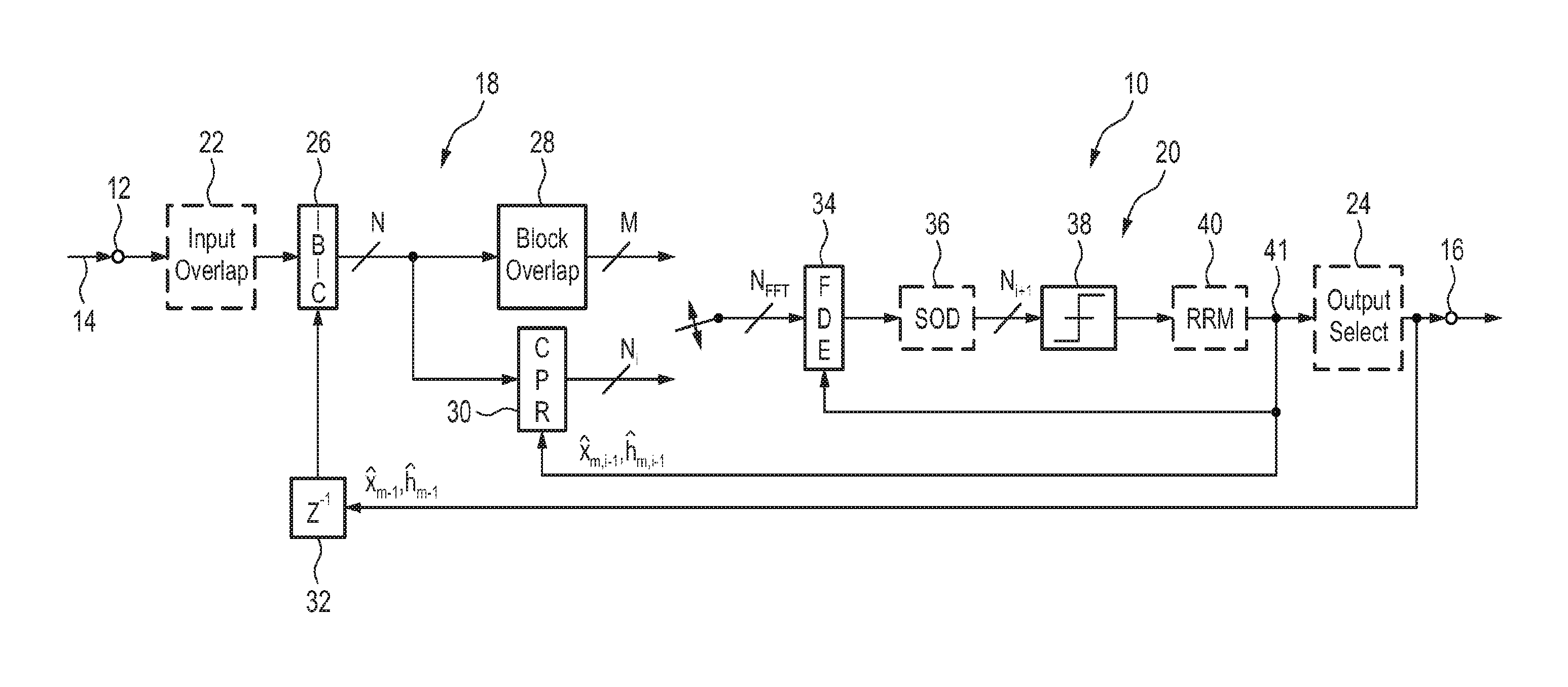
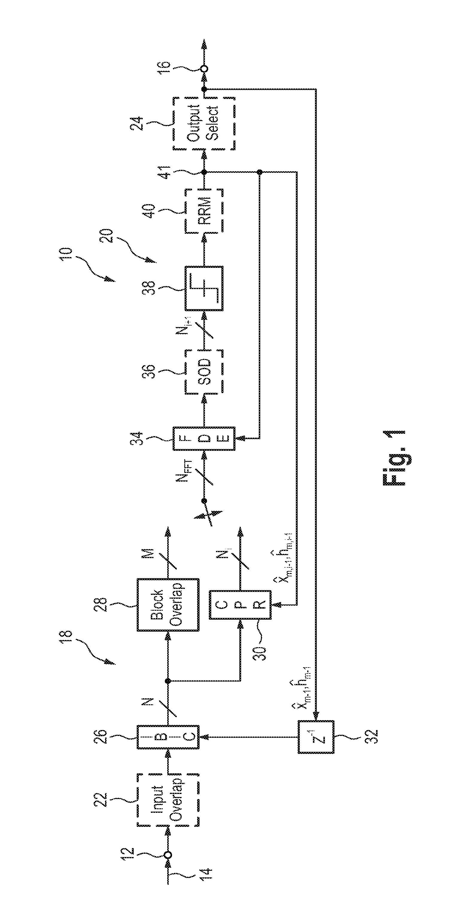
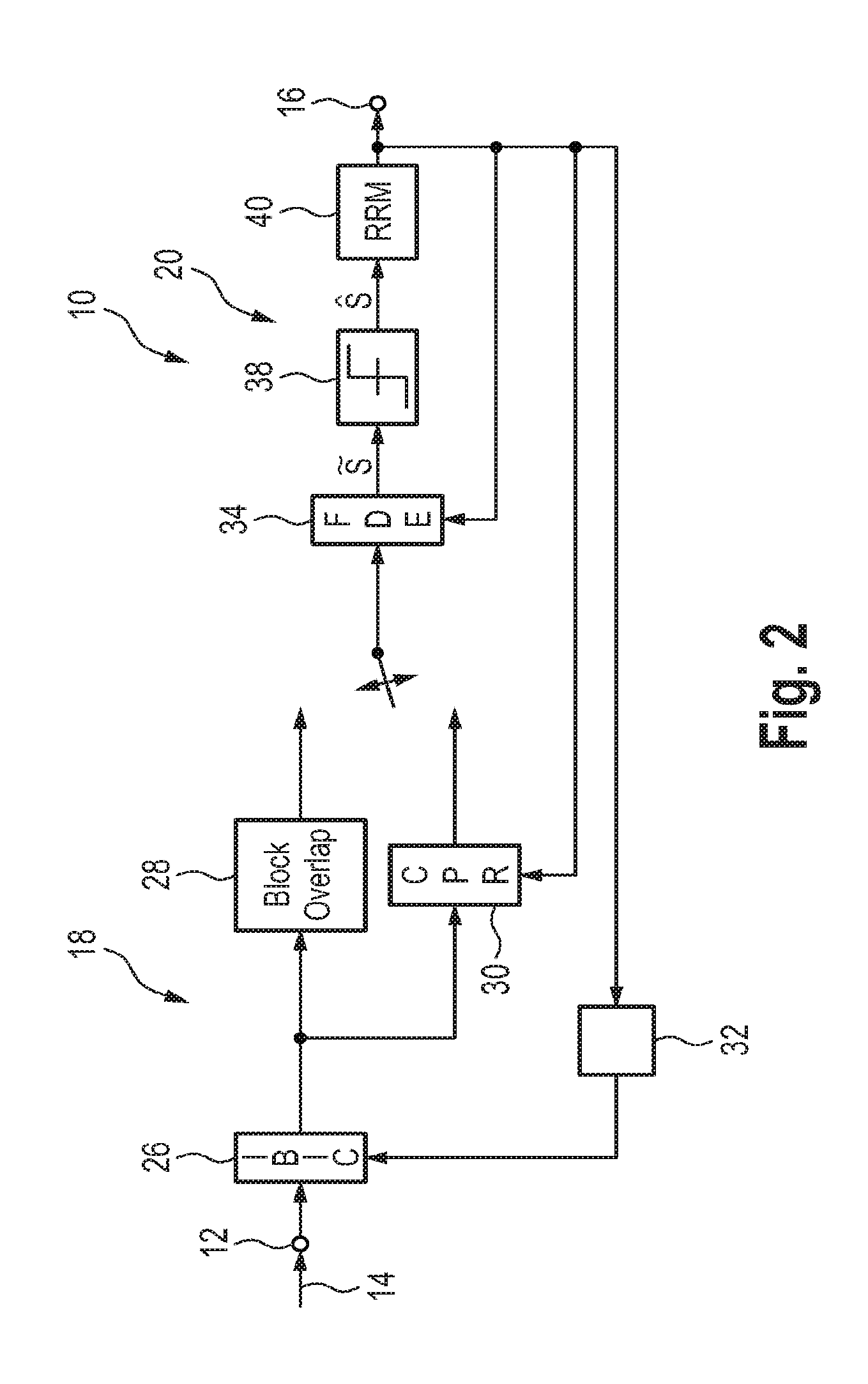
2. The receiver unit as defined in embodiment 1, further comprising a frequency domain equalizer configured to provide equalized symbols, wherein the a symbol detection circuit is configured to detect the subset of data symbols on the basis of the equalized symbols.
3. The receiver unit as defined in any preceding embodiment, wherein the reliability measuring circuit is configured to determine the reliability value on the basis of a difference between the equalized symbols and the detected subset of data symbols and / or the plurality of possible symbols.
4. The receiver unit as defined in any preceding embodiment, wherein the reliability measuring circuit is configured to determine the reliability value on the basis of an Euclidean distance or a Log-Likelihood-Ratio between the equalized symbol and the detected symbol and / or the plurality of possible symbols.
5. The receiver unit as defined in any preceding embodiment, wherein the reliability measuring circuit is configured to determine...
embodiment 12
13. The receiver unit as defined in embodiment 12, further comprising a cyclic prefix reconstruction circuitry connected to the feedback loop and configured to receive the detected data symbols.
14. The receiver unit as defined in embodiment 12 or 13, wherein the overlapping block separation circuit is configured to separate one half of the overlapping signal block.
15. The receiver unit as defined in any of the embodiments 12 to 14, wherein the overlapping block separation circuit is configured to remove a plurality of overlapping blocks in a plurality of iteration steps.
16. The receiver unit as defined in any of the embodiments 12 to 15, wherein the overlapping block separation circuit is configured to determine a length of the overlapping end part on the basis of a channel impulse response.
17. The receiver unit as defined in any of the embodiments 12 to 16, further comprising a processing block generation circuit configured to determine processing blocks, wherein each processing bl...
embodiment 18
19. The receiver unit as defined in embodiment 18, further comprising an inter-block interference canceller connected to the processing block generation circuit for receiving the processing blocks.
20. The receiver unit as defined in embodiment 18 or 19, wherein the processing block generation circuit is configured to determine the length of the overlapping part being identical with or smaller than the channel impulse response.
21. The receiver unit as defined in any of the embodiments 18 to 20, further comprising an output selection circuitry connected to receive a processed processing block and configured to remove a part of the processed processing block corresponding to the overlapping part.
22. A receiving method comprising:
[0122]receiving a receive signal including a plurality of data symbols,
[0123]detecting a subset of data symbols by means of a symbol detection circuit,
[0124]determining a reliability value for the data symbols,
[0125]detecting the subset of data symbols and / or t...
PUM
 Abstract
Description
Claims
Application Information
 - R&D
- Intellectual Property
- Life Sciences
- Materials
- Tech Scout
- Unparalleled Data Quality
- Higher Quality Content
- 60% Fewer Hallucinations
Browse by: Latest US Patents, China's latest patents, Technical Efficacy Thesaurus, Application Domain, Technology Topic, Popular Technical Reports.
© 2025 PatSnap. All rights reserved.Legal|Privacy policy|Modern Slavery Act Transparency Statement|Sitemap|About US| Contact US: help@patsnap.com


