Smoke detector with performance reporting

Active Publication Date: 2005-01-04
JOHNSON CONTROLS TYCO IP HLDG LLP
View PDF8 Cites 49 Cited by
  • Summary
  • Abstract
  • Description
  • Claims
  • Application Information

AI Technical Summary

Benefits of technology

A smoke detector according to the present invention comprises a smoke detecting chamber, an operating circuit for sensing smoke particles in the chamber and producing an alarm signal based on the sensed smoke particles. The smoke detector has electrical circuitry, including a coil, used when an alarm signal is produced, an input receiver for initiating a test in response to a test signal being received, an evaluation arrangement for determining operating characteristics of the operating circuit which vary over times and a controller for reporting the determined operating characteristics of the smoke detector in response to a test signal being received. The controller codes a pulsed signal with said determined operating characteristics and uses the coded pulsed signal to drive said electrical coil. The coded pulsed signal causes the electrical coil to produce a coded low power RF signal which includes the determined operating characteristics. The coded RF signal is receivable within a short distance of the smoke detector.
In the present invention, the cost to produce the coded RF signal is low as the transmitting coil or components necessary for a different function, are already present, and used in as part of the secondary function.
A smoke detector according to a preferred aspect of the invention comprises a smoke detecting chamber, an arrangement for sensing smoke particles in the chamber, an evaluation arrangement for evaluating the operating characteristics of the arrangement for sensing smoke particles, and transmitting a coded signal in a weak RF signal in response to a test signal being received by the detector. The smoke detector has a sound generator used to indicate a sensed alarm condition. The sound generator has a drive circuit associated therewith which amplifies a pulsed signal to provide a drive signal for the sound generator. The smoke detector includes a controller for reporting status information of the smoke detector in response to a user activating the test actuator. The controller codes the pulse signal used to generate the drive signal. This coding is done with the status information of the smoke detector. The coded pulse signal causes the drive circuit to produce a low power RF signal which includes the coded status information. The coded RF signal is capable of being accurately received within a short distance of the smoke detector. In a preferred embodiment the signal is designed to be received by a portable receiver within approximately a two foot radius of the smoke detector.

Problems solved by technology

It is also possible to update or replace the alarm panel, however, in many cases, this is not practical from a cost standpoint as the entire alarm system is typically replaced.
Dust accumulation within the sensing chamber of the smoke detector can seriously affect the performance characteristics of the detector.
This early warning avoids false alarms which are expensive and also reduce the reliability of the system.
Unfortunately, the performance monitoring of the smoke detectors includes data which is not reported to the alarm control panel as at the time of manufacture of the alarm control panel, this type of data may not have been available or that the detectors did not report this type of data to the alarm control panel.
This situation is compounded in that new detectors which may be added to a system cannot report this information to an old style alarm panel and it is difficult to justify replacement of the alarm control panel.
The separate outputting of performance data of a smoke detector allows this data to be received and analyzed, however, a substantial cost of the detector has increased.
The additional cost for providing a smoke detector with its own RF transmitter and / or other data output device, does improve the monitoring function of the device, however, there is a substantial cost penalty which renders the system less competitive.
Monitoring of only some of the smoke detectors is not a complete solution.

Method used


Image

  • Smoke detector with performance reporting
  • Smoke detector with performance reporting
  • Smoke detector with performance reporting

Examples


Embodiment Construction

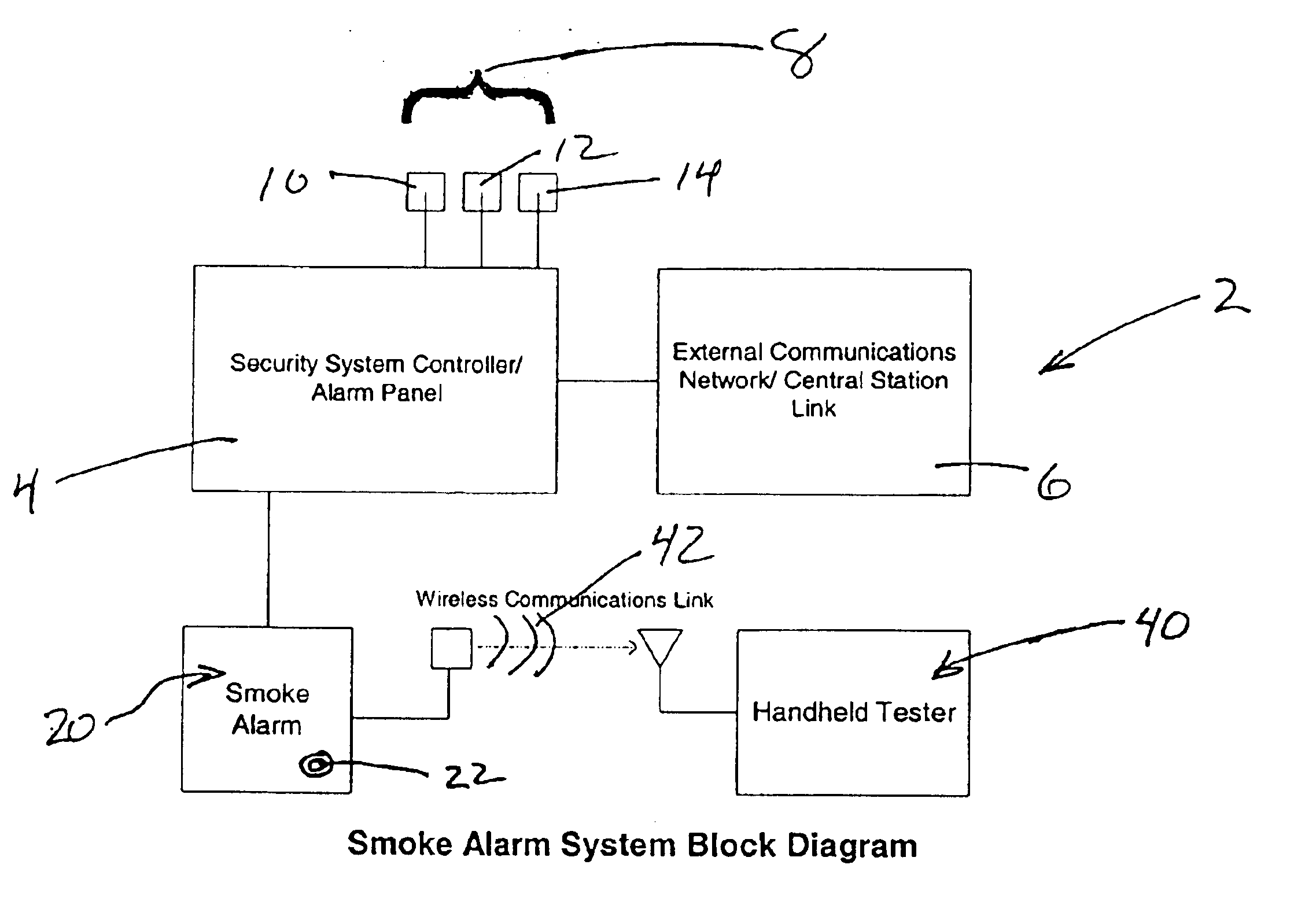
The alarm system 2 as shown in FIG. 1, includes an alarm panel 4 which basically receives and processes signals from the various peripheral devices 8, including sensors 10, key pads 12 and sounders 14. The alarm panel 4 also cooperates with an external communication network generally shown as 6 for communicating with a central station. This central station processes the various signals from alarm panels and undertakes appropriate action such as alerting of police or other emergency or response services.

Alarm systems of this general type have been known for many years and are extremely popular for home and business applications.

Smoke detectors used in association with this type of alarm system, are subject to decreasing performance due to age and decreasing performance due to environmental contaminations such as dust, etc. Smoke detectors, if not properly serviced, can cause false alarms or require immediate attention at inconvenient times. For this reason, it is known to test alarm ...


PUM


Abstract

A cost effective system for testing smoke detectors and determining and communicating the operating characteristics thereof, advantageously uses existing circuitry components in a secondary communication function. With this arrangement, a low powered RF reporting signal is transmitted from the smoke detector and can be received within several feet of the detector. Preferably the RF signal is produced by a pulsed input signal provided to an existing coil which is part of the circuitry used to produce and / or report alarm signals. A receiving arrangement is also disclosed which can be located in close proximity to a smoke detector which has been activated to report the operating characteristics thereof. These characteristics can then be analyzed to determine whether preventive maintenance is appropriate.

Description

FIELD OF THE INVENTIONThe present invention relates to alarm systems and smoke detectors used in alarm systems and in particular, relates to downloading of performance information from such smoke detectors.BACKGROUND OF THE INVENTIONAlarm systems are used by consumer and industrial users to provide improved safety and security of residences and industrial facilities. These alarm systems typically include an alarm panel which receives and monitors signals from a host of peripheral devices, including keypads, various sensors and warning devices. The control panels, upon receiving notice of an alarm condition typically report to a remote central station over a telephone line or other communication path.Alarm systems can be divided into hard wire systems where the alarm panel is hard wired to the various peripheral devices such as smoke detectors, motion detectors, etc., or a wireless system where these devices communicate with the alarm panel using RF transmissions, for example. In wir...

Claims


Application Information

Patent Timeline
IPC IPC(8): G08B29/00G08B29/14
CPCG08B29/145
Inventor LENNARTZ, GARYSINGLETON, SCOTT
Owner JOHNSON CONTROLS TYCO IP HLDG LLP
Why Eureka
Try Eureka