
Photographing device and method

a technology of a photographing device and a camera body, which is applied in the field of photographing devices and methods, can solve the problems of inability to appropriately perform transfer, inability to use the imaging system of other users, and failure to appropriately transmit samples, etc., and achieve the effect of quick information of users and preventing useless imaging

Active Publication Date: 2016-09-01
FUJIFILM CORP
View PDF0 Cites 7 Cited by
  • Summary
  • Abstract
  • Description
  • Claims
  • Application Information

AI Technical Summary

Benefits of technology

The invention is an imaging device and method that can quickly inform a user if there is a problem with the creation of a sample. By calculating the exposure time needed to get the image signal to the target level and checking if it exceeds a threshold, the device can determine if the sample was created correctly or if there is not enough light emitted from it. This saves time and prevents unnecessary imaging. The technical effect of this invention is to improve the efficiency and accuracy of the imaging process.

Problems solved by technology

For example, in a case where a result of electrophoresis of fluorescence-labeled protein on a gel support is imaged with the above-described imaging system, while an operation to transfer fluorescence-labeled protein on the gel support to a membrane is performed, the transfer may not be appropriately performed and sample creation may fail.
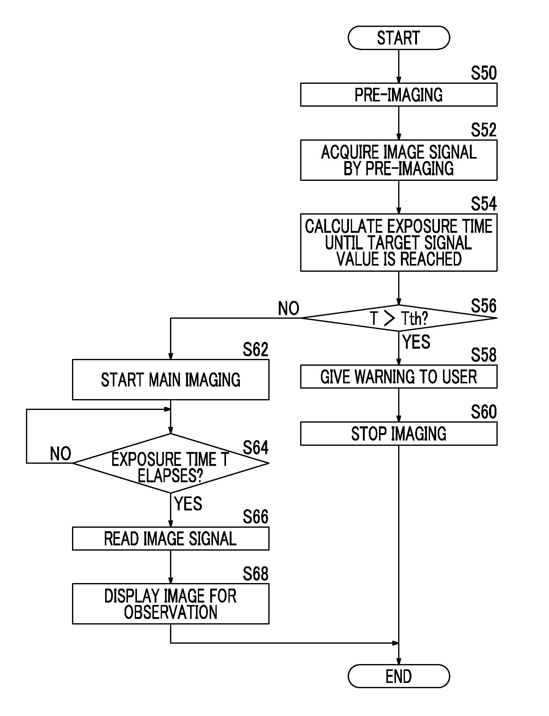
In general, since fluorescence emitted from a fluorescent label is weak, in a case where an image of fluorescence is imaged, a comparatively long exposure time is required until a target signal value is obtained; however, as described above, if imaging is performed over a long exposure time even when sample creation fails, the user wastes time, the use of the imaging system of other users is uselessly inhibited, and the use efficiency of the imaging system is degraded.
JP2014-39116A has suggested that, for imaging an object using an imaging element, a remaining exposure time until appropriate exposure is completed is calculated, and the remaining exposure time is displayed and informed to the user; however, there is no suggestion of a method which prevents useless imaging due to failure of sample creation described above.

Method used


Image

  • Photographing device and method
  • Photographing device and method
  • Photographing device and method

Examples


first embodiment

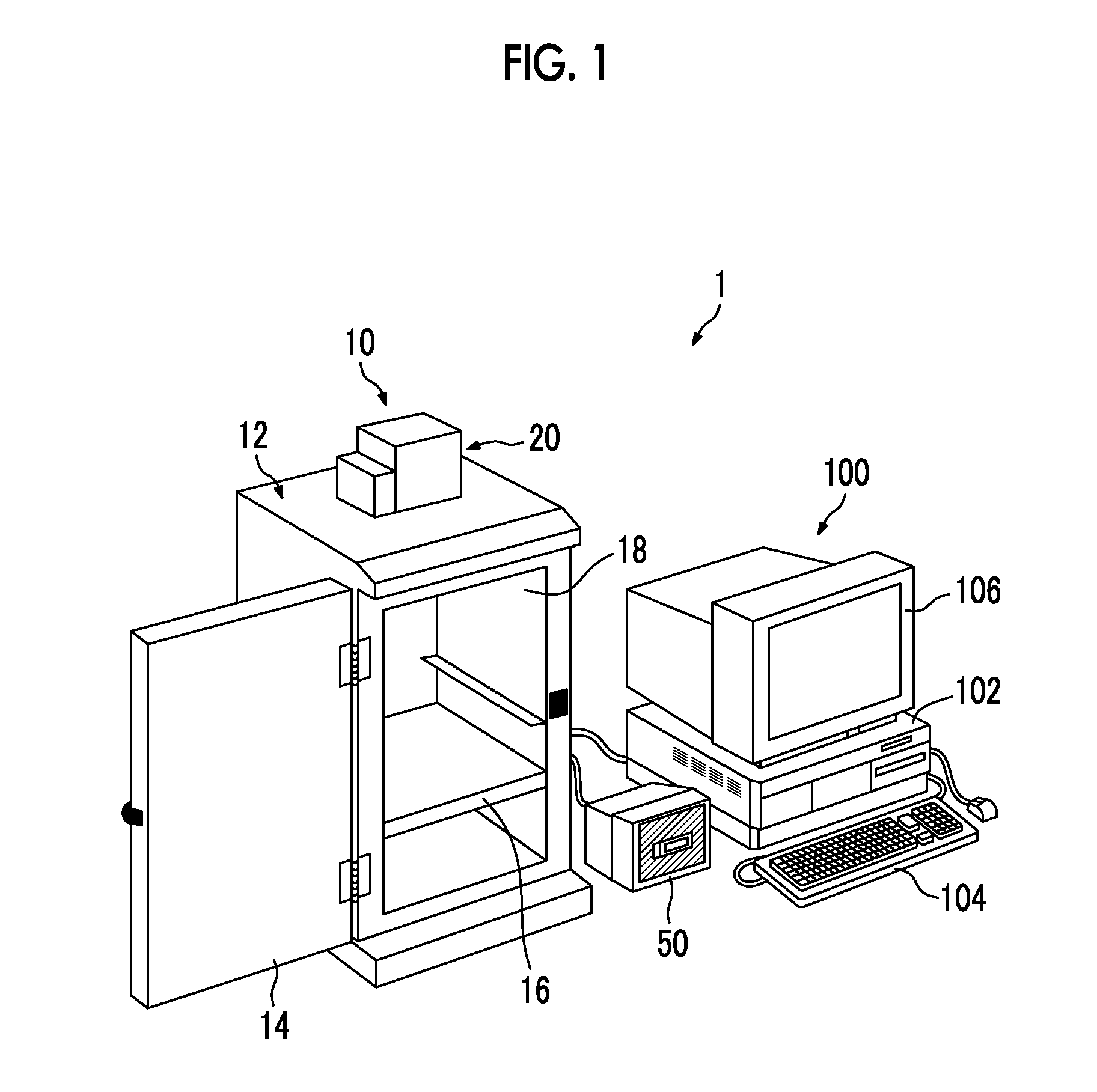
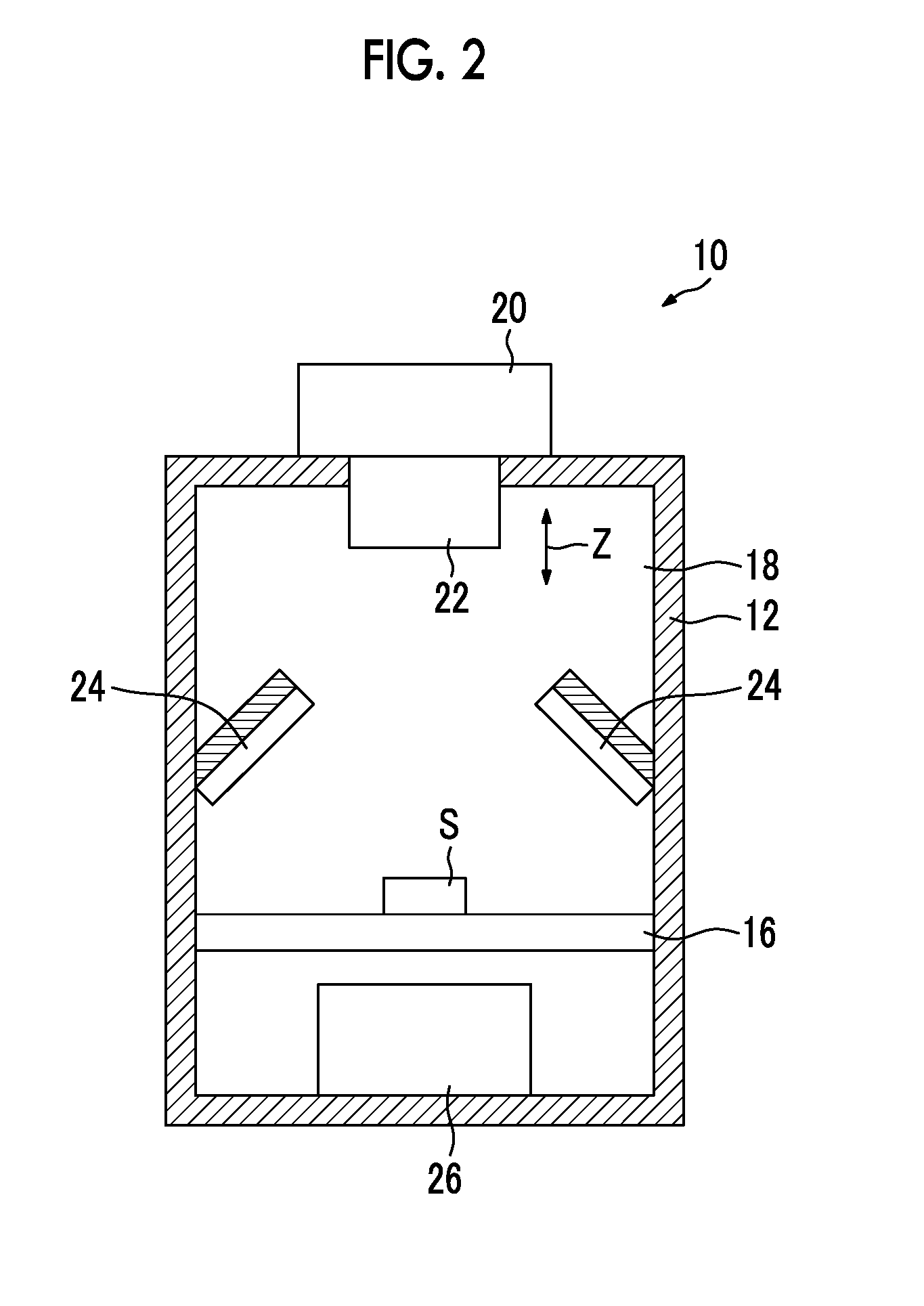
[0033]Hereinafter, an imaging system 1 using an imaging device and method of the invention will be described in detail referring to the drawings. FIG. 1 is a schematic perspective view showing an imaging system of this embodiment, FIG. 2 is a schematic sectional view showing the internal configuration of an imaging device of this embodiment, and FIG. 3 is a schematic block diagram showing the imaging system of the embodiment.

[0034]As shown in FIGS. 1 and 2, the imaging system 1 of this embodiment includes a black box 10 and an imaging control device 100.

[0035]The black box 10 includes a housing 12 having a door 14, a stage 16 on which an object S is placed, an imaging unit 20, a lens unit 22, an epi-illumination light source unit 24, a transmission light source unit 26, and an object observation monitor 50.

[0036]The housing 12 has a hollow portion 18 which is formed in a substantially rectangular parallelepiped, and is provided with the stage 16 on which the object S is arranged. Th...

second embodiment

[0086]As in the second embodiment, in a case where the image signal is acquired by the pre-imaging, the display control unit 115 may make the display unit 106 display an image for confirmation based on the image signal acquired by the pre-imaging. In this way, in a case where the image for confirmation is displayed, the user can confirm failure of sample creation visually.

[0087]In the first and second embodiments, when the threshold value determination is performed in the determination unit 112, the threshold value Tth may be changed between in a case where an image of chemiluminescence of the object S is imaged and in a case where an image of fluorescence of the object S is imaged. This is because, for imaging an image of fluorescence, excitation light is reflected from the support or the like, a signal value of an image signal of a background by reflected light is great, and even if there is no fluorescence, the imaging element is likely to be saturated. In this way, since there i...


PUM

PropertyMeasurementUnit
exposure timeaaaaaaaaaa
thresholdaaaaaaaaaa
fluorescenceaaaaaaaaaa

Abstract

Disclosed is a imaging device and method capable of quickly informing a user of failure of sample creation and preventing useless imaging from being performed. The imaging device includes an imaging unit which images an object, an exposure time calculation unit which calculates, based on an image signal acquired by imaging of the imaging unit, an exposure time of the imaging until a signal value of the image signal reaches a target signal value set in advance, a determination unit which determines whether or not the exposure time exceeds a threshold value set in advance, and a display control unit which, in a case where it is determined that the exposure time exceeds the threshold value set in advance, gives notification of the result of the determination.

Description

CROSS-REFERENCE TO RELATED APPLICATIONS[0001]The present application claims priority under 35 U.S.C. §119 to Japanese Patent Application No. 2015-038295, filed on Feb. 27, 2015. Each of the above application(s) is hereby expressly incorporated by reference, in its entirety, into the present application.BACKGROUND OF THE INVENTION[0002]1. Field of the Invention[0003]The present invention relates to an imaging device and method which images light emitted from an object with an imaging element.[0004]2. Description of the Related Art[0005]Hitherto, an imaging system which arranges an object in a housing and irradiates an object with light using a light source in the housing to image the object has been used in various fields.[0006]Among such imaging systems, an imaging system which selectively uses an imaging method according to the type of object, and images, for example, chemiluminescence, fluorescence, or reflected light from the object, or transmitted light transmitted through the o...

Claims


Application Information

Patent Timeline
Patent Type & Authority Applications(United States)
IPC IPC(8): H04N5/235H04N5/347G01N21/64H04N5/232H04N25/46
CPCH04N5/2356H04N5/2351G01N21/6456H04N5/347H04N5/23293G03B7/093G03B17/18H04N23/634H04N23/71H04N23/73H04N23/74H04N25/46H04N23/743
Inventor TANAKA, YASUTAKEOHTA, YASUNORI
Owner FUJIFILM CORP
Learn More