Sealing ring for gyratory crusher
- Summary
- Abstract
- Description
- Claims
- Application Information
AI Technical Summary
Benefits of technology
Problems solved by technology
Method used
Image
Examples
Embodiment Construction
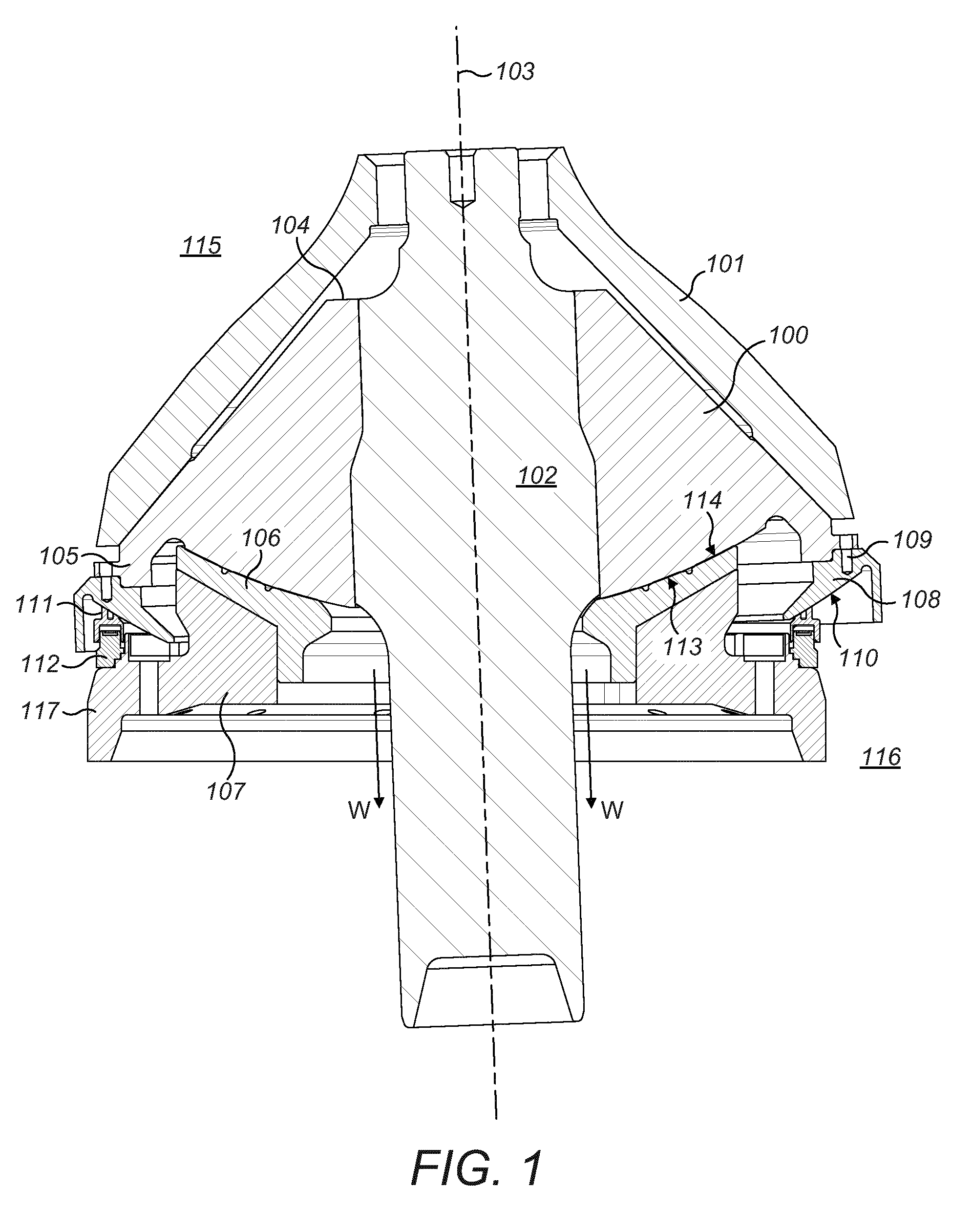
[0029]FIG. 1 illustrates a perspective view of selected components of a gyratory crusher at the region of the crushing zone 115 defined within a main frame of the crusher. In particular, an elongate main shaft 102 is intended to extend longitudinally through the crusher and comprises longitudinal axis 103. A generally conical shaped crushing head 100 is mounted about shaft 102 that, in turn, mounts an inner crushing shell 101 (typically referred to as a mantle). Head 100 comprises an axially upper annular end 104 and an axially lower annular end 105. A generally dish-shaped axially lowermost surface 113 of head 100 is positioned in contact with an annular bearing 106 and in particular bearing surface 114. Bearing 106 is mounted at an annular bearing support 107 positioned axially below head 100 and bearing 106. Accordingly, head 100 and inner crushing shell 101 are capable of reciprocating gyroscopic precession as the two contact surfaces 113, 114 slide over one another during crush...
PUM
 Abstract
Description
Claims
Application Information
 - R&D
- Intellectual Property
- Life Sciences
- Materials
- Tech Scout
- Unparalleled Data Quality
- Higher Quality Content
- 60% Fewer Hallucinations
Browse by: Latest US Patents, China's latest patents, Technical Efficacy Thesaurus, Application Domain, Technology Topic, Popular Technical Reports.
© 2025 PatSnap. All rights reserved.Legal|Privacy policy|Modern Slavery Act Transparency Statement|Sitemap|About US| Contact US: help@patsnap.com


