
Compliant elastomeric shock absorbing apparatus

a technology of elastomeric shock absorbers and shock absorbers, which is applied in the direction of shock absorbers, dampers/dampers, dampers-spring combinations, etc., can solve the problems of increased scrap, increased downtime of blow molding apparatus, and additional maintenan

Active Publication Date: 2016-07-28
ITT MFG ENTERPRISES LLC
View PDF6 Cites 2 Cited by
  • Summary
  • Abstract
  • Description
  • Claims
  • Application Information

AI Technical Summary

Benefits of technology

The patent describes a shock absorbing apparatus that uses a flexible housing and a plate with a single orifice to create chambers containing hydraulic fluid that are connected by the orifice. The apparatus also includes one or more mounting plates to connect the housing to a structure or machine that is under load. When a shock load is transmitted, the elastomeric housing is pressurized and the contained hydraulic fluid moves through the orifice to provide energy dissipation through viscous damping. The apparatus is simpler and easier to assemble, perform reliably, and has a longer service life compared to prior designs. It is also easier and cheaper to manufacture and assemble. Different applications can use the same components and manufacturing process tools.

Problems solved by technology

Such bounce can produce defects in the molded product resulting in increased scrap, additional maintenance and increased downtime of the blow molding apparatus.
Consequently, the throughput / efficiency of the blow molding apparatus is adversely impacted.
Inasmuch as blow molding or other apparatus routinely undergo a high number of cycles, it is common for the dynamic seals to fail prematurely, requiring costly repair and maintenance.
Additionally, the replacement of either the hydraulic seals, or the entire shock absorber assembly, can adversely impact manufacturing schedules or other time-critical events for the purpose of repairing and / or replacing the affected assemblies.

Method used


Image

  • Compliant elastomeric shock absorbing apparatus
  • Compliant elastomeric shock absorbing apparatus
  • Compliant elastomeric shock absorbing apparatus

Examples


Embodiment Construction

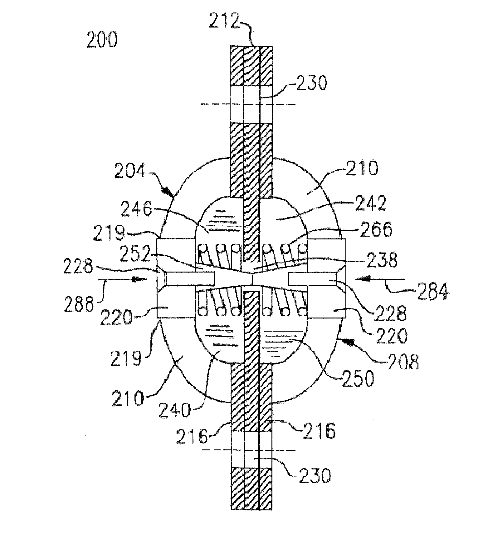
[0034]The following relates to certain embodiments of a shock absorbing apparatus that relies upon at least one elastomeric element or membrane to define a highly flexible housing containing a hydraulic fluid that can be attached to a structure or machine under load. The apparatus reliably reduces transmitted shock loads from other parts of a machine or other structure. In one embodiment, a reciprocating piston or piston assembly is eliminated along with the requirement for dynamic seals. In other embodiments, a compression assembly is fully immersed within, or enveloped by, a flexible membrane or housing. In these embodiments, immersion of the compression assembly allows for a degree of fluid leakage or passage from one cavity to an adjacent cavity.

[0035]In certain embodiments, the shock absorbing apparatus reduces transmitted shock loads without the requirement for sliding dynamic seals to move a hydraulic fluid through a damping orifice and / or separate spring biasing elements to ...


PUM


Abstract

A shock absorbing apparatus includes a flexible membrane defining an accumulator cavity, and a compression assembly defining a compression cavity. The compression assembly is disposed within the flexible membrane such that viscous fluid contained within the cavities may be exchanged therebetween by a damping orifice, fluid conduit and or valve mechanism. The accumulator cavity deforms in response to the application of a transmitted impact load, and is capable of storing and releasing potential energy in response to the application and cessation of the transmitted impact load.

Description

CROSS-REFERENCE TO RELATED APPLICATION[0001]This application claims priority under relevant portions of 35 U.S.C. §119 to U.S. Patent Application Ser. No. 62 / 107,766, filed Jan. 26, 2015, the entire contents of which are herein incorporated by reference.TECHNICAL FIELD[0002]This application is generally directed to the field of energy absorption apparatus and more specifically to a shock absorbing apparatus that employs a highly flexible housing containing a quantity of hydraulic fluid. The housing is defined by at least one elastomeric membrane to limit forces transmitted to the surroundings of an attached structure, but without requiring dynamic hydraulic seals or separate spring biasing apparatus.BACKGROUND[0003]There are several types of apparatus that can be employed for industrial and structural uses in order to absorb energy, such as from a transmitted load. For example, high cycle blow molding apparatus employ mold or die halves which can “bounce” as a consequence of opening...

Claims


Application Information

Patent Timeline
IPC IPC(8): F16F9/22F16F13/10F16F9/516F16F13/00F16F9/19
CPCF16F9/22F16F13/007F16F13/10F16F9/516F16F9/19F16F13/08F16F13/24
Inventor KUDLA, CHRISTOPHERKELLY, JEFFREY T.DOWNING, MARSHALL W.KOSCIELNIAK, JOHN T.WEISBECK, JEFFREY N.
Owner ITT MFG ENTERPRISES LLC
Learn More