Light Guiding Device

a light guiding device and light guiding technology, applied in semiconductor devices, lighting and heating apparatus, instruments, etc., can solve the problems of user disturbance, inhomogeneity, and light deflected by the light guiding device is relatively outcoupled

Active Publication Date: 2016-07-21
SMR PATENTS S A R L
View PDF14 Cites 78 Cited by
  • Summary
  • Abstract
  • Description
  • Claims
  • Application Information

AI Technical Summary

Benefits of technology

The invention is a light guiding device that can be used in an illumination device to produce a more uniform or "homogenous" illumination. The device has a light incoupling side, a reflection side, and a light outcoupling side. The reflection layer is a paint or lacquer layer that is imprinted or evaporation-coated on the reflection side. The reflection layer can be made of the same material as the rest of the device. The light guiding device can be used in an illumination device in a motor vehicle, such as an indicator device of a rearview device. The device can also be a blind spot monitor for the vehicle. The invention provides a solution for creating a more uniform or "homogenous" illumination.

Problems solved by technology

In known light guiding devices, it has proven disadvantageous that the light deflected by the light guiding device is outcoupled relatively inhomogeneously over a surface to be illuminated.
As the line width of the pictogram increases, 1.0 mm for example, the inhomogeneity becomes quite visible and the user finds it disturbing.
In the extreme case, a very non-uniform illumination of a pictogram can cause the user to misinterpret an indicator light as not illuminated.

Method used


Image

  • Light Guiding Device
  • Light Guiding Device
  • Light Guiding Device

Examples


Embodiment Construction

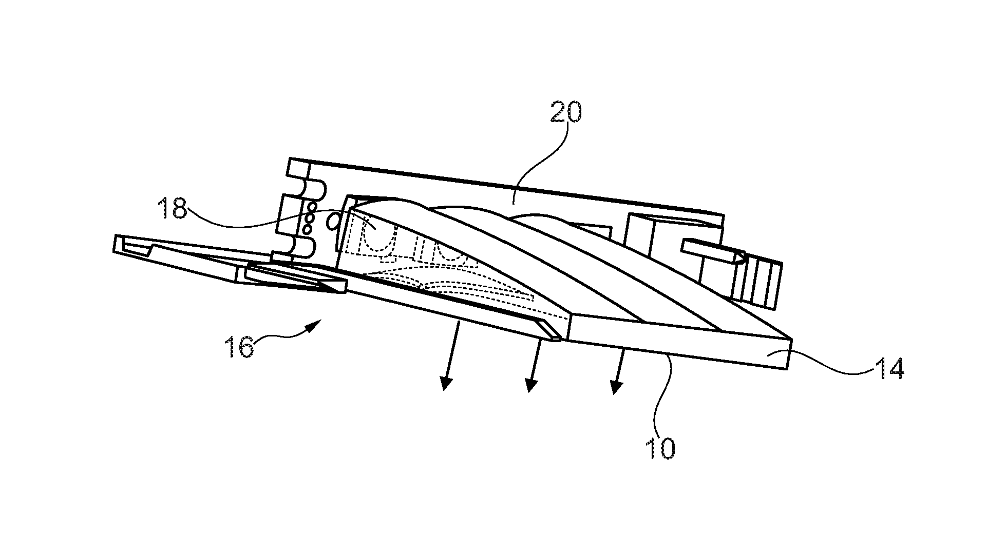
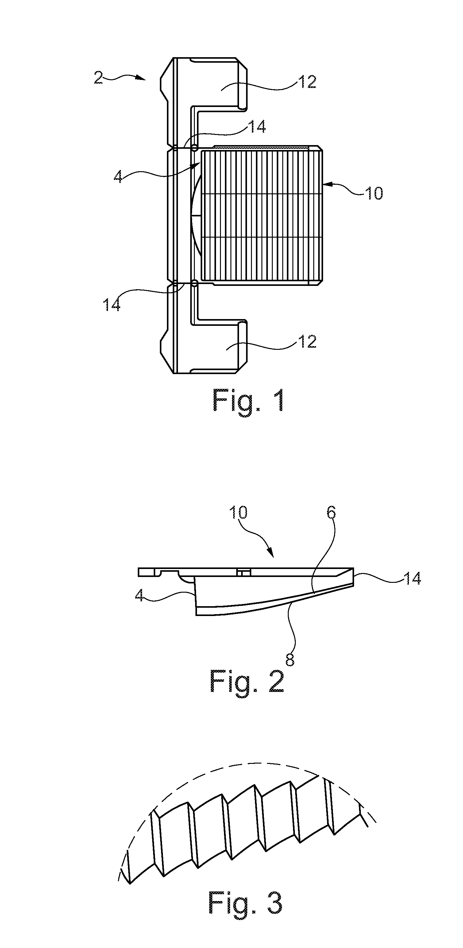
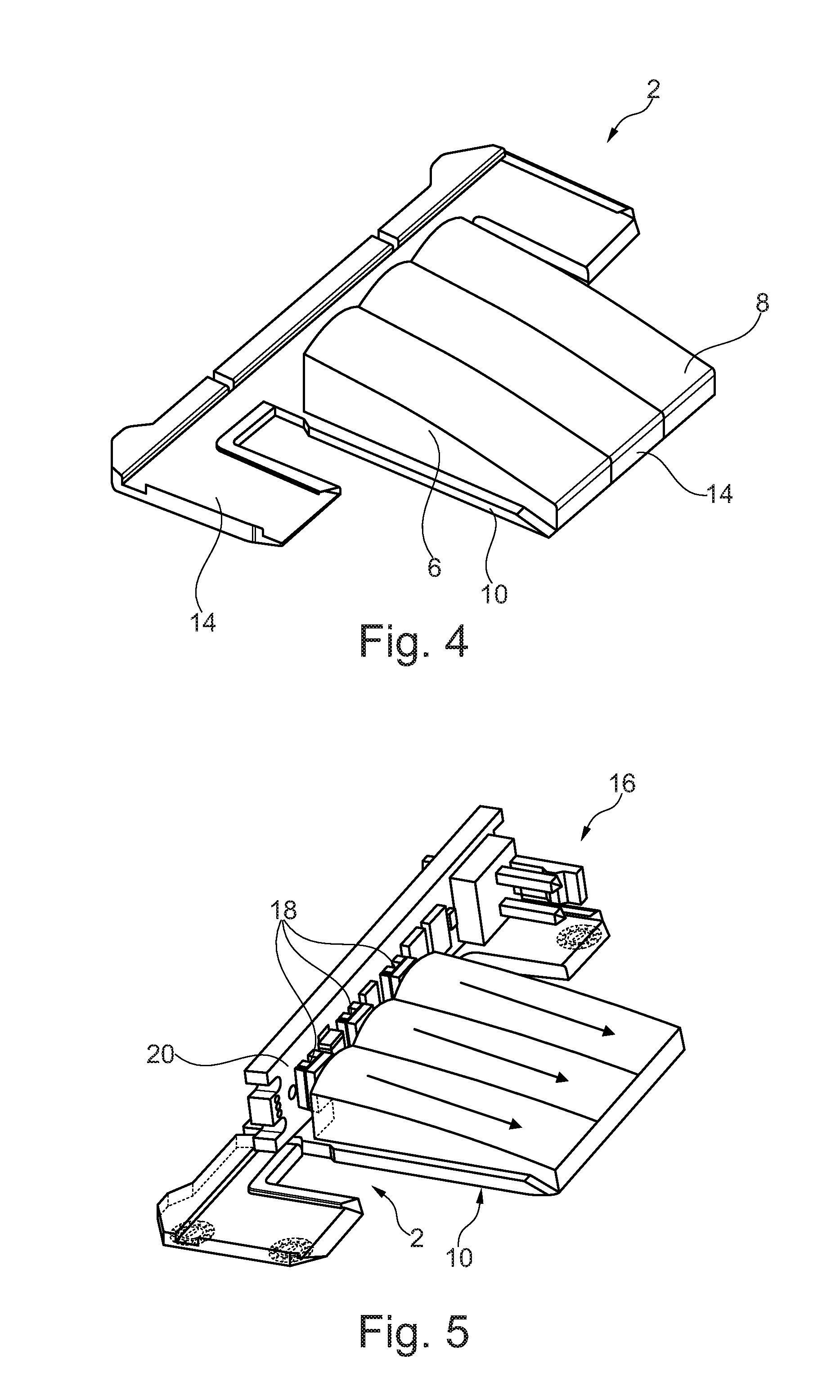
[0033]FIG. 1 depicts a top view of a light guiding device 2 having a light incoupling side 4, a reflection side 6, a reflection layer 8 (see FIG. 2), and a light outcoupling side 10. In the top view of FIG. 1 the reflection side 6 is disposed under the light outcoupling side 10 and the reflection layer 8 is disposed under the reflection side 6. The light outcoupling side 10 is disposed opposite the reflection side 6 and therefore also opposite the reflection layer 8, so that reflected light reaches the light outcoupling side 10 as uniformly as possible. The clearance between the light outcoupling side 10 and the reflection side 6 and therefore also the reflection layer 8 decreases as the distance from the light incoupling side 4 increases. The light outcoupling side 10 and the reflection side 6 can thus converge continuously or form an edge 14 that can also have a reflection layer 8.

[0034]By way of example FIG. 1 moreover depicts two holding devices 12, which extend away from the li...


PUM


Abstract

A light guiding device for an illumination device, especially for a motor vehicle or an indicator device in a rearview device of a motor vehicle includes a light coupling side for incoupling light from a light source, a reflection side having a reflection layer; and a light outcoupling side, which is disposed generally opposite the reflection side. A clearance between the reflection side and the light outcoupling side generally decreases as the distance from the light incoupling side increases. The reflection side having the reflection layer is configured so that light arriving from the light incoupling side is deflected to the light outcoupling side. The reflection layer may be a paint or lacquer layer that is imprinted or evaporation-coated on the reflection side.

Description

CROSS-REFERENCE TO RELATED APPLICATIONS[0001]This application claims the benefit of European Patent Application No. EP 15151604.4, filed Jan. 19, 2015, the disclosure of which is incorporated herein by reference in its entirety.BACKGROUND OF THE INVENTION[0002]The invention relates to a light guiding device for an illumination device, such as a backlight or interior or exterior lighting, wherein incident light is deflected by reflection. The light guiding device can particularly be used in an indicator of a motor vehicle, in connection with a blind spot monitor in an outside mirror for example. The invention also relates to a like illumination device, an outside mirror having such a light guiding device and a method for producing such a light guiding device.[0003]In known light guiding devices, it has proven disadvantageous that the light deflected by the light guiding device is outcoupled relatively inhomogeneously over a surface to be illuminated. This effect becomes ever more obv...

Claims


Application Information

Patent Timeline
Patent Type & Authority Applications(United States)
IPC IPC(8): F21V7/00B60Q1/52F21V7/22B60Q1/26F21V9/08F21W107/10
CPCF21V7/0091B60Q1/2665B60Q1/2607B60Q1/525B60Q1/2696F21V7/22F21V9/08F21V7/24F21Y2115/10F21W2107/10F21V2200/00B60R1/1207G02B6/0046G02B6/0055G02B6/0078F21S43/14F21S43/239F21S43/249F21S43/315
Inventor KURSCHNER, NORBERTFRITZ, DANIEL
Owner SMR PATENTS S A R L
Why Eureka
Try Eureka