Signal connector having grounding member for pressing and preventing from short-circuit

a technology of grounding member and connector, which is applied in the direction of coupling device details, coupling device connection, electric discharge lamp, etc., can solve the problems of endangering the life and property of users, affecting the safety of users, and electric short-circuit certainly will occur, so as to prevent elastic fatigue and permanent deformation, improve usage safety, and prevent short-circuit

Active Publication Date: 2016-07-14
GUIMA SCI & TECH
View PDF0 Cites 19 Cited by
  • Summary
  • Abstract
  • Description
  • Claims
  • Application Information

AI Technical Summary

Benefits of technology

The present invention aims to provide a clamping mechanism for a metal grounding member in an insulating body. The metal grounding member has a front end with clamping parts and a rear end with protrusions. When the insulating body is assembled into the second accommodating space, the metal grounding members and the protrusions are tightly abutted against the insulating body to ensure a stable connection. The intervals between the metal grounding members and the metal housing allow for movements and deformations within a range, which prevents elastic fatigue of the clamping parts. The design prevents elastic fatigue of the clamping parts and ensures a reliable and durable connection between the metal grounding members and the insulating body.

Problems solved by technology

Therefore, electric short-circuit certainly will be occurred easily because the conductors (such as connection terminals, grounding members, a metal housing, and so on) inside the USB Type-C connector are too close to each other, and may result in damage of the related electronic components and endanger safety of the user's life and property.
In addition, while using the USB Type-C connector, the user usually plug and pull the connector frequently and such actions are easy to cause elasticity loss of the connection terminals of the Type-C connector.

Method used


Image

  • Signal connector having grounding member for pressing and preventing from short-circuit
  • Signal connector having grounding member for pressing and preventing from short-circuit
  • Signal connector having grounding member for pressing and preventing from short-circuit

Examples


Embodiment Construction

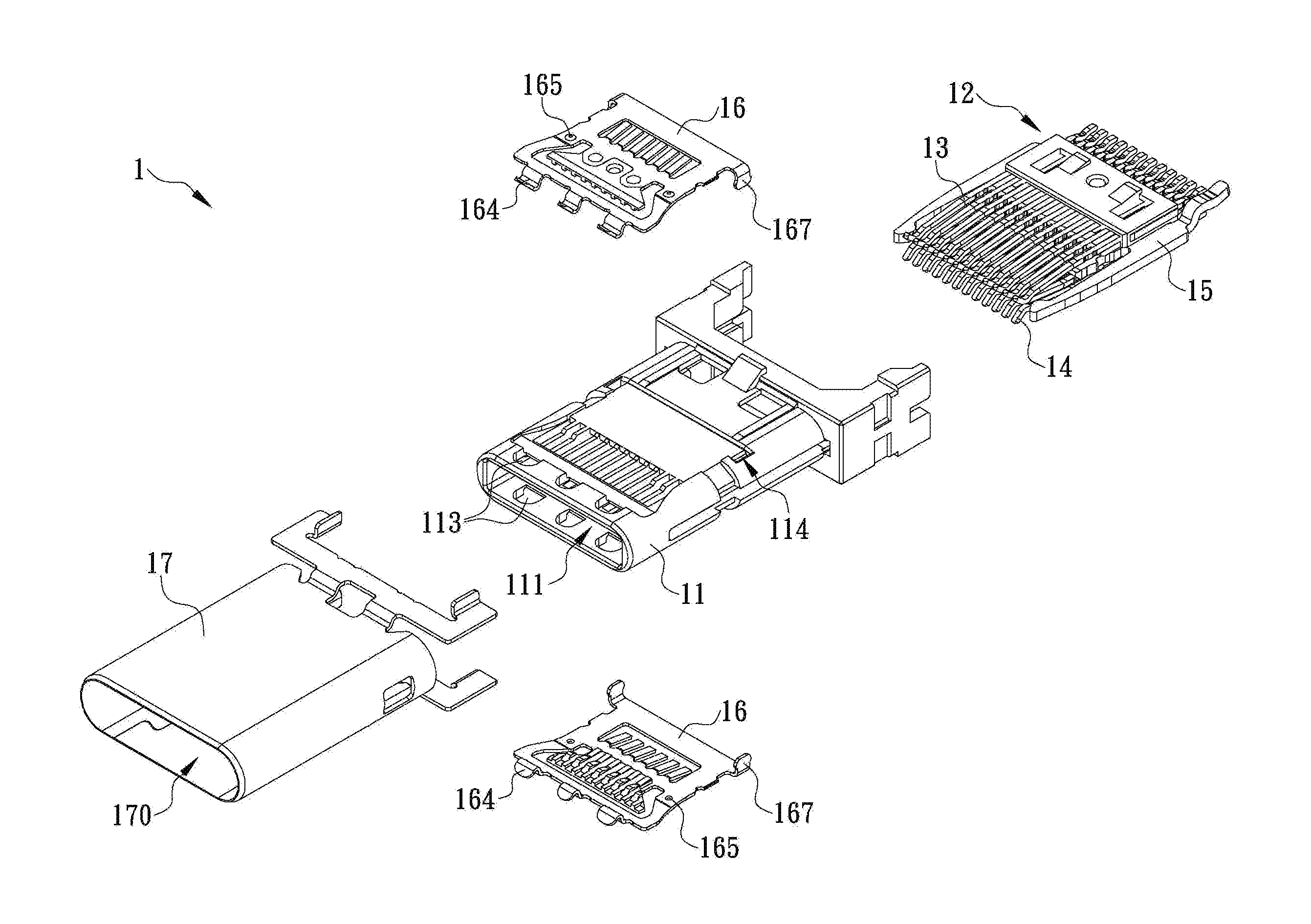
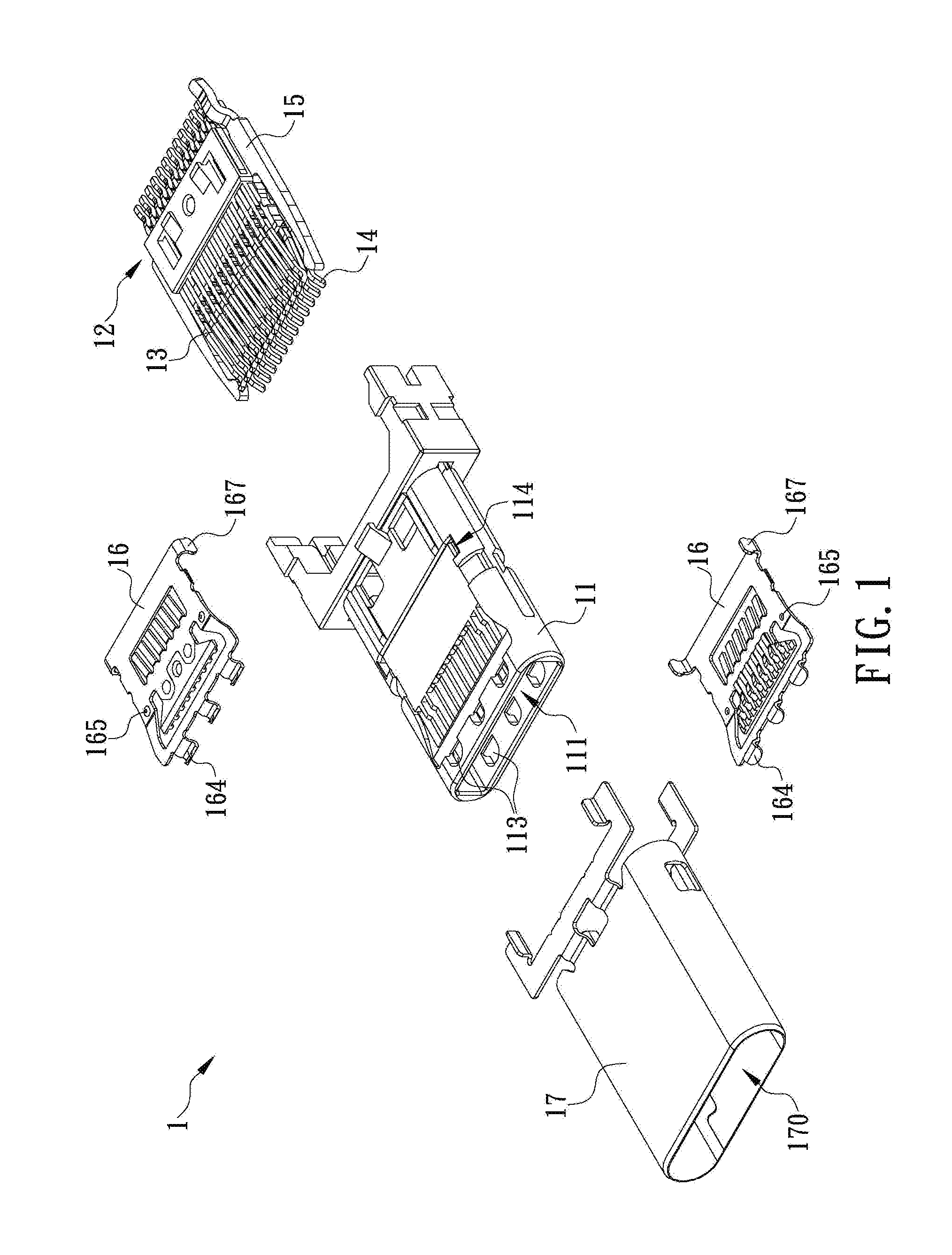
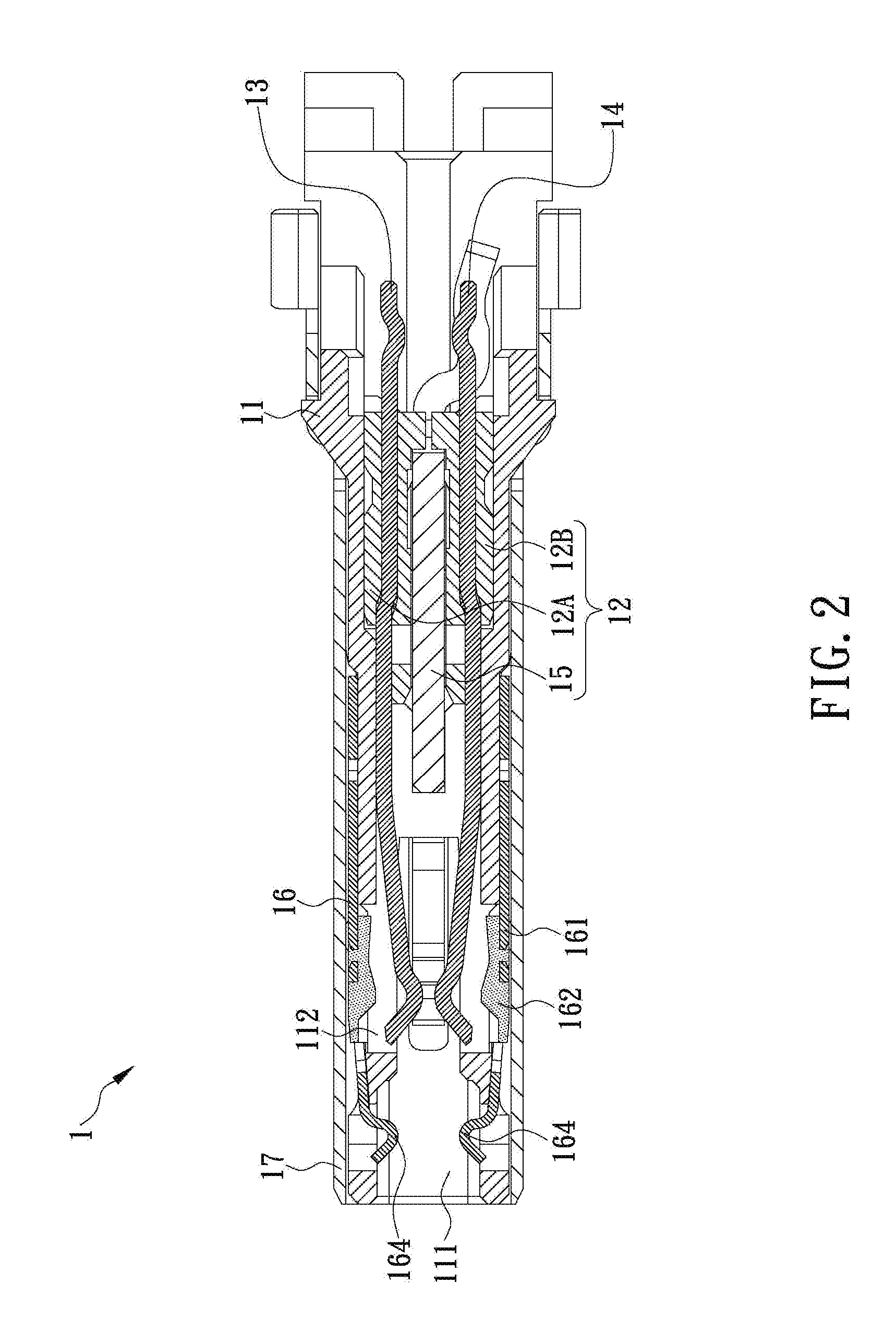
[0015]Reference will now be made in detail to the exemplary embodiments of the present disclosure, examples of which are illustrated in the accompanying drawings. Therefore, it is to be understood that the foregoing is illustrative of exemplary embodiments and is not to be construed as limited to the specific embodiments disclosed, and that modifications to the disclosed exemplary embodiments, as well as other exemplary embodiments, are intended to be included within the scope of the appended claims. These embodiments are provided so that this disclosure will be thorough and complete, and will fully convey the inventive concept to those skilled in the art. The relative proportions and ratios of elements in the drawings may be exaggerated or diminished in size for the sake of clarity and convenience in the drawings, and such arbitrary proportions are only illustrative and not limiting in any way. The same reference numbers are used in the drawings and the description to refer to the ...


PUM


Abstract

The present invention is to provide a signal connector which includes an insulating body having a plurality of through grooves cut through top and bottom surfaces thereof adjacent to a front end thereof; an insulating terminal seat mounted inside the insulating body and having a plurality of metal terminals fastened thereon and separated from each other; two metal grounding members having rear ends respectively assembled with the top and bottom surfaces of the insulating body, having pressing parts respectively formed adjacent to front ends thereof and corresponding in position to the through grooves and having insulating layers respectively covered on side surfaces thereof facing the through grooves; such that the pressing part is able to apply a restoring force on the metal terminal when the signal connector is plugged with other signal connector and the metal terminal is moved away from the insulating terminal seat through the corresponding through groove.

Description

FIELD OF THE INVENTION[0001]The present disclosure generally relates to a signal connector, more particularly to a signal connector having grounding member for pressing and preventing from short-circuit, which is able to effectively prevent a plurality of metal terminals installed therein from elastic fatigue and permanent deformation, so as to ensure the quality of electric connection provided by the signal connector, prevent the associated electronic device from being damaged because of electric short-circuit and then greatly improve the usage safety and extend the endurability of the signal connector.BACKGROUND OF THE INVENTION[0002]With the rapid development of information technology and of the electronic industry, various kinds of electronic devices (such as a tablet computer, smartphone, driving recorder, and so on) with excellent qualities, reasonable prices, compact sizes and light weights have become important and indispensable tools for most people in daily life and work. ...

Claims


Application Information

Patent Timeline
Patent Type & Authority Applications(United States)
IPC IPC(8): H01R13/56H01R24/70
CPCH01R24/70H01R13/56H01R13/6582H01R24/60
Inventor CHEN, SHIH-JUI
Owner GUIMA SCI & TECH
Why Eureka
Try Eureka