
Mount apparatus

a technology of mounting apparatus and mounting bracket, which is applied in the direction of machine supports, jet propulsion mounting, other domestic objects, etc., can solve the problems of larger apparatus and heavier apparatus, and achieve the effects of space saving, weight saving and excellent fatigue strength

Active Publication Date: 2016-07-14
YAMASHITA RUBBER CO LTD +1
View PDF5 Cites 5 Cited by
  • Summary
  • Abstract
  • Description
  • Claims
  • Application Information

AI Technical Summary

Benefits of technology

The present invention is for a mount apparatus that is designed to save space, save weight, and have excellent fatigue strength. The apparatus includes attachment parts and a vibration receiving part, both made of resin, to achieve these goals. The vibration receiving part is supported by a dropout prevention plate fixed to the car body, which prevents it from dropping out. This also prevents the formation of sound caused by beating and friction between the vibration receiving part and the dropout prevention plate. An elastic member is preferably used to further prevent collisions between the vibration receiving part and the dropout prevention plate, and a rib is added to strengthen the binding force of the dropout prevention plate to the vibration receiving part. These features improve strength, durability, and prevent misalignment or unexpected dropout of the elastic member. Overall, the mount apparatus offers space and weight savings while being strong and durable.

Problems solved by technology

However, there is a problem that, if the mount apparatus is of the suspended type, the size of the apparatus will be larger and the apparatus will be heavier, in order to ensure a fatigue strength.

Method used


Image

  • Mount apparatus
  • Mount apparatus
  • Mount apparatus

Examples


Embodiment Construction

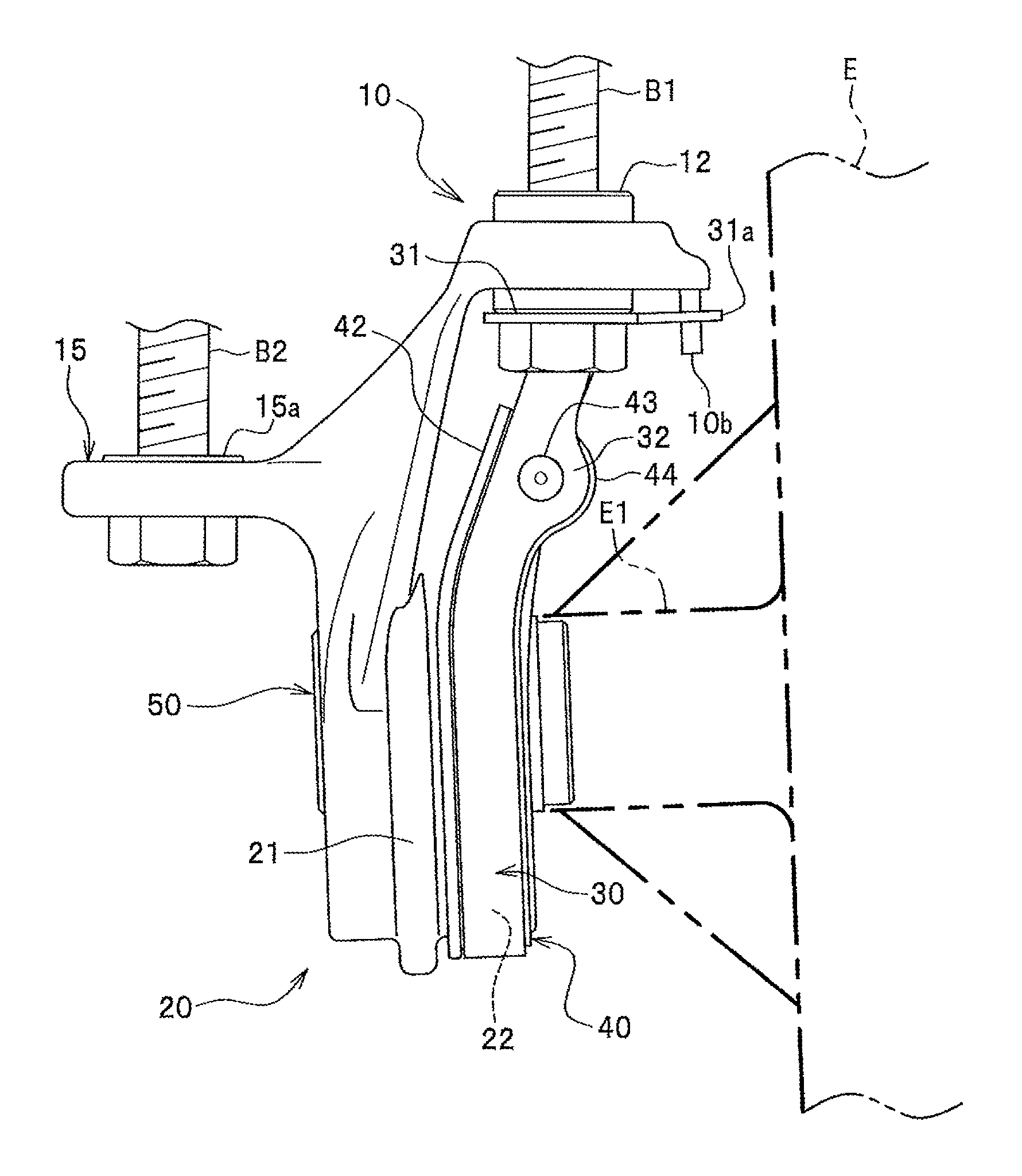
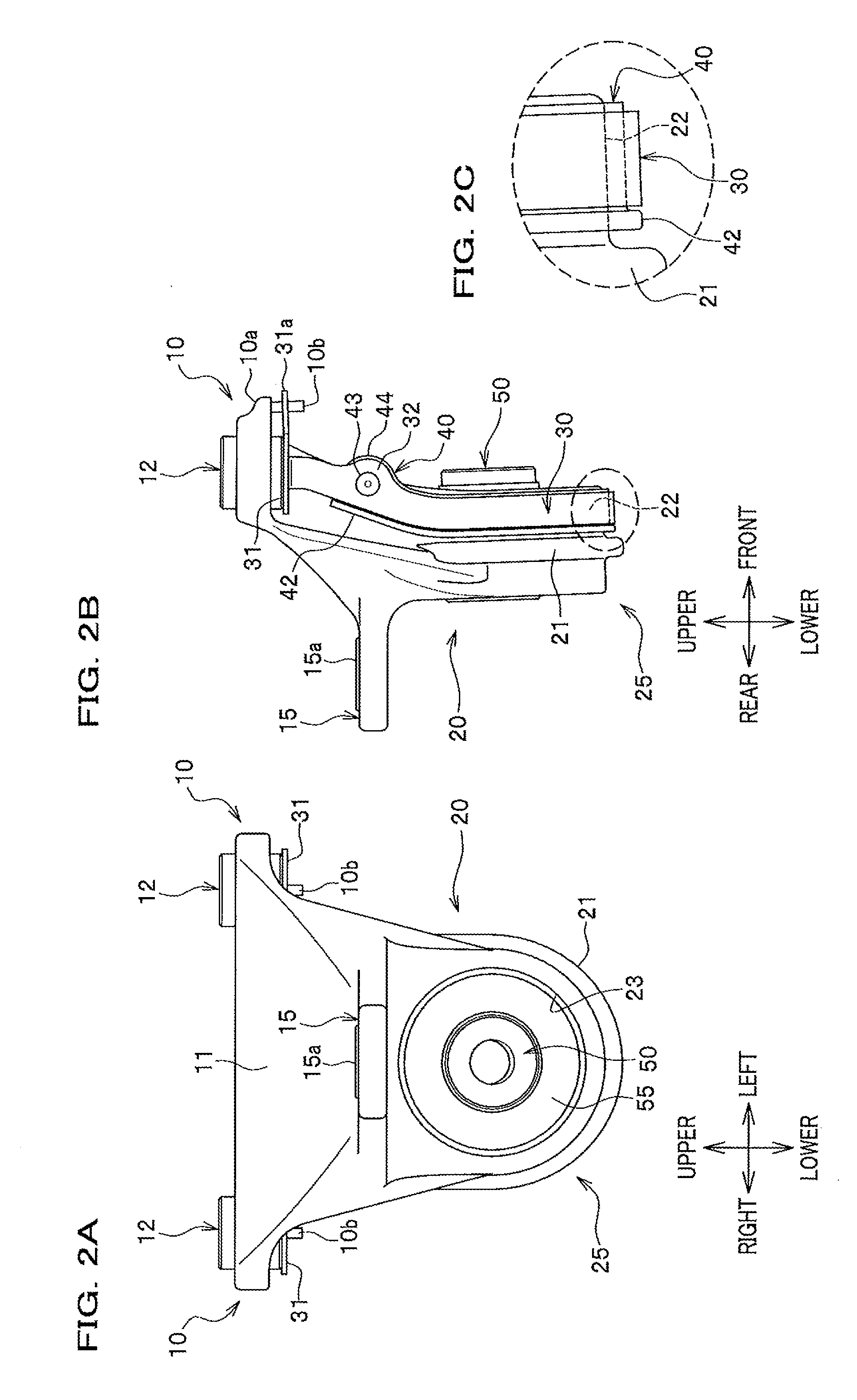
[0023]Embodiments of a mount apparatus according to the present invention will be described with reference to the drawings. In the following description, although the words “front / rear”, “right / left” and “upper / lower” are used on the basis of directions depicted in FIG. 1, they do not necessarily coincide with real installation condition. In the description, the same reference numerals are used for the same elements, and duplicated description is omitted.

[0024]As shown in FIGS. 1A to 1C, a mount apparatus is of a suspended type, comprising a pair of attachment parts 10, 10, a vibration receiving part 20, a dropout prevention plate 30 and an elastic member 40. The pair of attachment parts 10, 10 and the vibration receiving part 20 are made of resin, which are integrally molded when they are molded.

[0025]The attachment parts 10 are regions to be attached to a frame, etc. of a body side. The attachment parts 10 have a flange shape. An insertion hole 11 (see FIG. 1B) is formed in each a...


PUM


Abstract

A mount apparatus that achieves both space saving and weight saving and is excellent in fatigue strength, is provided. The mount apparatus comprises a pair of attachment parts to be attached to a car body, a vibration receiving part, fixed to the attachment parts, for receiving input vibrations from a vibration source through an elastic material, and a dropout prevention plate supporting the vibration receiving part, the attachment parts and the vibration receiving part being made of resin, wherein the dropout prevention plate is arranged so as to cover an outer surface of the vibration receiving part at a predetermined interval from the outer surface of the vibration receiving part, wherein both ends of the dropout prevention plate is fixed through the pair of attachment parts to the car body.

Description

CROSS REFERENCE TO RELATED APPLICATIONS[0001]This application claims priority to Japanese Patent Application No. 2015-003979 filed on Jan. 13, 2015, the entire contents of which are incorporated by reference herein.BACKGROUND OF INVENTION[0002]1. Technical Field[0003]The present invention relates to a mount apparatus of a suspended type.[0004]2. Related Art[0005]Conventionally, an apparatus as described in JPH06-54936(U) is known as a mount apparatus for supporting heavy goods such as an engine, electric motors, a differential gear, etc. of motorcars. This mount apparatus comprises an outer tube made of resin to which a rubber cushion is adhered by vulcanization, and a bracket made of metal surrounding an upper half surface of the outer tube and having an attachment part formed so as to be fixed to a body frame in its lower part.[0006]Incidentally, since the mount apparatus as described in JPH06-54936(U) has a structure to be mounted on the body frame, etc., space saving is desired ...

Claims


Application Information

Patent Timeline
Patent Type & Authority Applications(United States)
IPC IPC(8): F16F15/08B60K5/12F16M13/02
CPCF16F15/08B60K5/1208F16M13/02F16F1/3849
Inventor SAKAMOTO, KAZUYUKILINFIELD, BENJAMIN
Owner YAMASHITA RUBBER CO LTD
Learn More