
Tamper resistant bicycle lock

a bicycle lock and tamper-resistant technology, applied in the field of bicycle locks, can solve the problems of cycle complexity, no foolproof, and needing continued improvement of locks, and achieve the effects of reducing the potential for catastrophic crushing or breaking, high resistance to breakage, and convenient assembly

Inactive Publication Date: 2016-07-14
GEORGE DAVID L
View PDF8 Cites 9 Cited by
  • Summary
  • Abstract
  • Description
  • Claims
  • Application Information

AI Technical Summary

Benefits of technology

The present invention provides a bicycle lock with a shackle and base that are resistant to failure modes such as breakage, drilling, melting, and cutting. The use of nested discreet segments of internal materials, especially ceramic links and rods, reduces the likelihood of catastrophic crushing or breaking and simplifies assembly. The invention also takes advantage of the cost-effectiveness and developments in ceramic materials.

Problems solved by technology

Therefore, it requires continuing improvement in the locks developed to protect cycles, particularly as those cycles are more sophisticated and costly.
Of course, it is almost axiomatic that nothing is foolproof, or in this case “theft-proof”, so it often becomes a matter of trade-offs in cost, inconvenience for legitimate users, difficulty of defeat and the amount of time it takes to defeat any lock of similar theft-prevention structure.

Method used


Image

  • Tamper resistant bicycle lock
  • Tamper resistant bicycle lock
  • Tamper resistant bicycle lock

Examples


embodiment 10

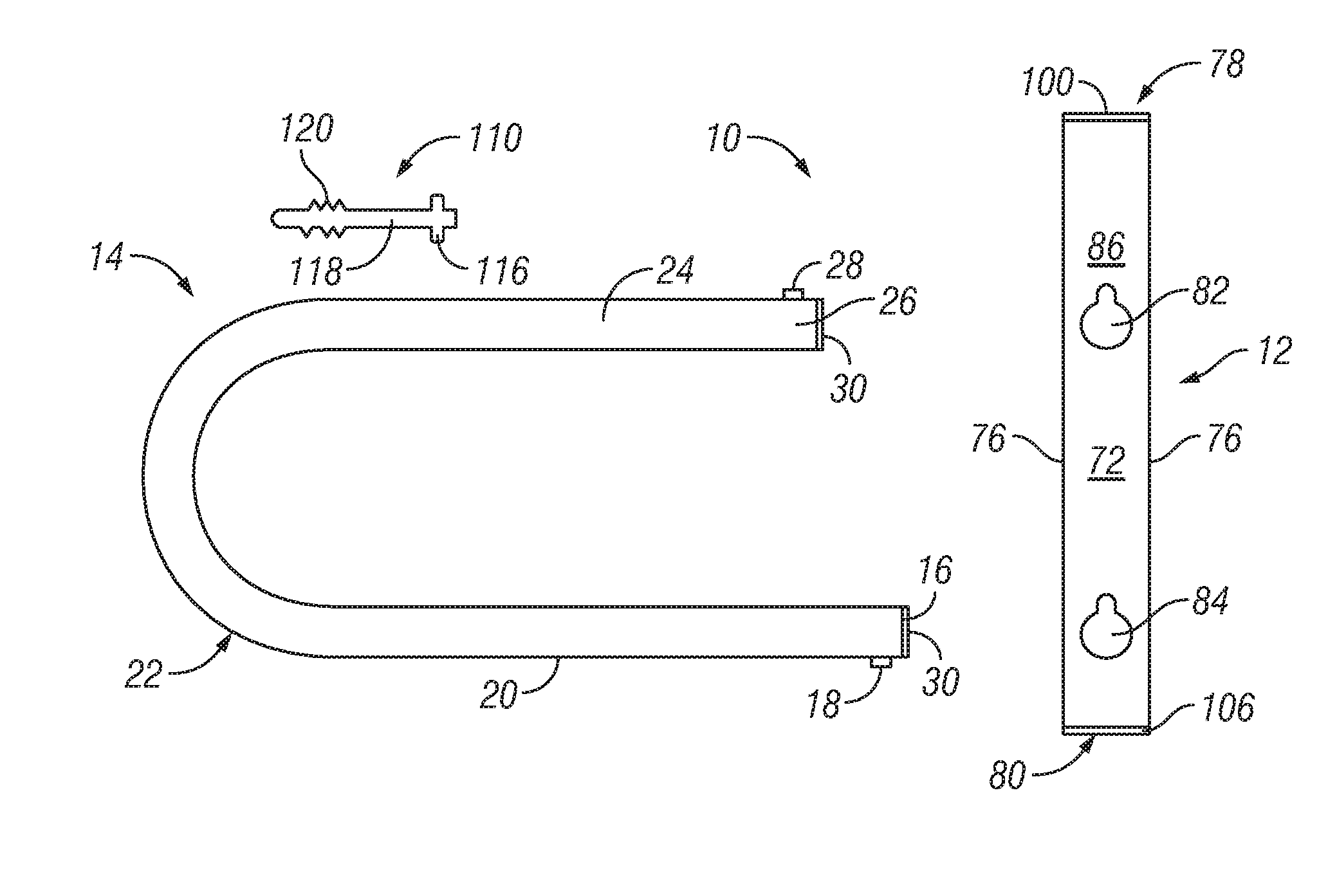
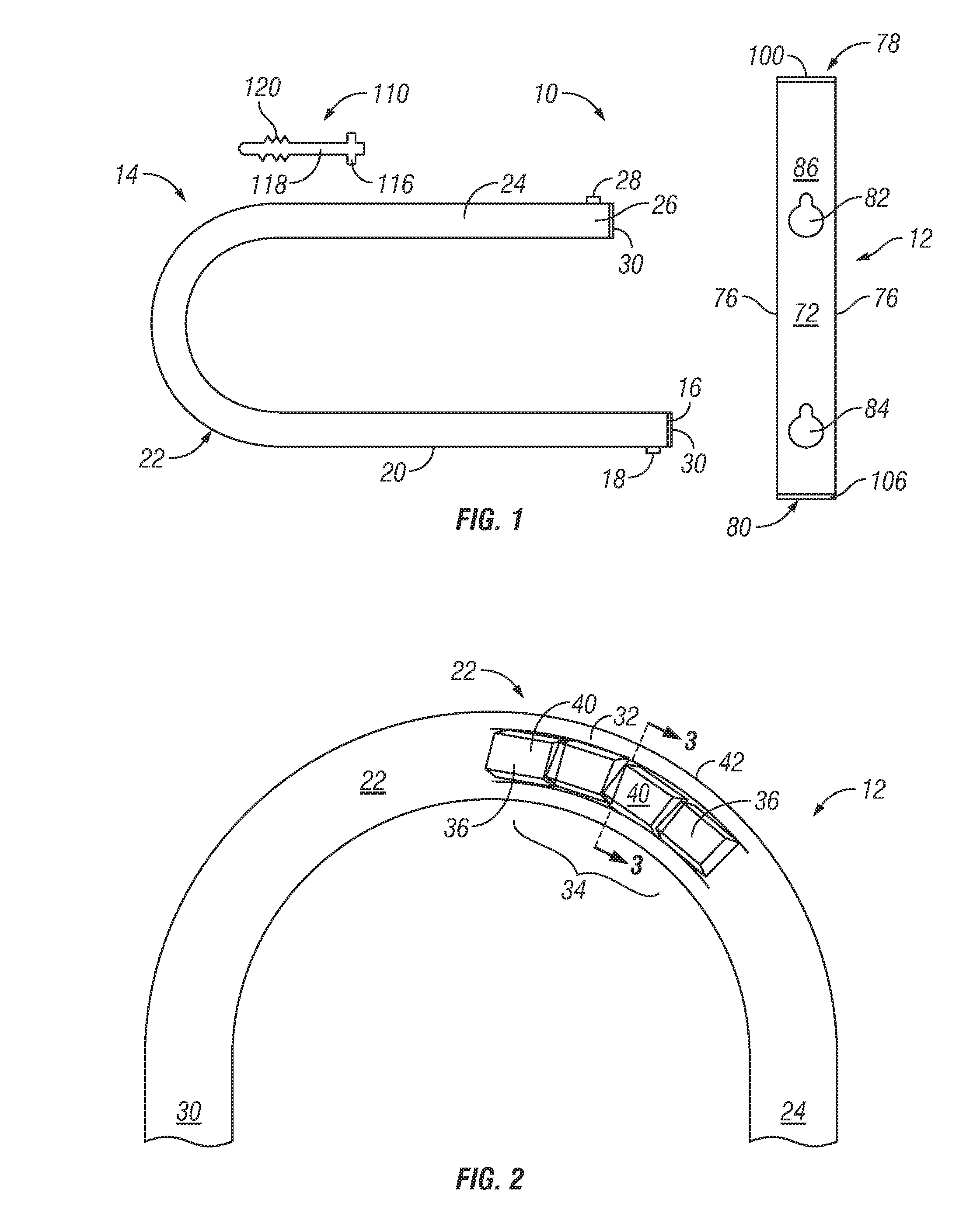
[0027]The shackle 14 is illustrated in the overall view of FIG. 1 and the more detailed views of FIGS. 2-4. The general structure of the shackle 14 is an elongated U-shape and is shown to have a pivot end 16 having a pivot detent 18, a first straight segment 20 extending to a central arc segment 22, and a second straight segment 24 extending to a free end 26. The free end 26 includes a lock detent 28. A bottom cap 30 closes each ends 16 and 26. The first straight segment 20 in the preferred embodiment 10 is longer than the second straight segment 24 such that the pivot end 16 will extend beyond the base 12 when engaged in the lock mode while the free end 26 will be captured within the base 12.

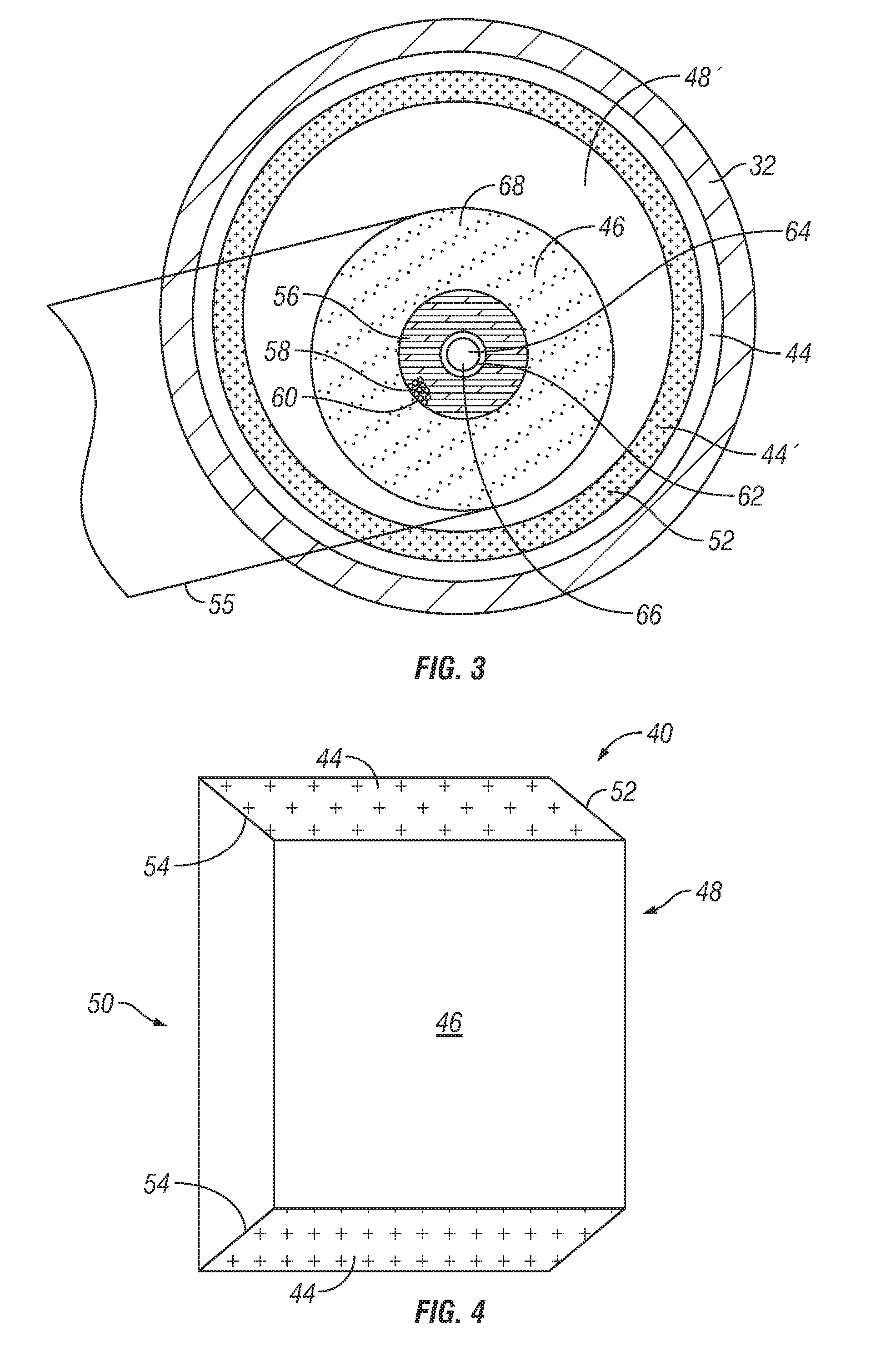
[0028]Referring now to FIGS. 2 and 3 the details of the shackle 14 are shown in a cut-away illustration of the arc segment 22 in FIG. 2 and in a cross-sectional view of FIG. 3. The shackle 14 is constructed with particular care to prevent destruction of its integrity by bolt cutters, diamond sa...

embodiment 12

[0046]FIG. 7, similar to FIG. 5 shows a deluxe embodiment 12′ of the base member (lock end). This illustration shows a ceramic sleeve 132 provided I the interior of the central bore 88 (see FIG. 6 which extends about the base 12′ from the first base end 78 to at least the free end aperture 82). The ceramic sleeve 132 proves additional cutting, sawing and drilling protection to the most vulnerable elements of the lock 10′. Similarly, a case hardened steel sheath 154 is provided to circumferentially surround the 12′ in the region of the lock cylinder subsystem 112 to provide additional protection against bolt cutters and the like.

[0047]While most of the internal components are the same as in the basic embodiment 12, the deluxe base 12′ includes an alternate cylinder guard subsystem 156 which includes both a first plug 158 and a second plug 160. The first plug 158 can be identical to the layered plug 134 of FIG. 5, complete with a reaction spring 150, while the second plug 160 may be l...


PUM


Abstract

A tamper resistant bicycle lock (10) is provided having a base (12) and a shackle (14) each provided with an interior ceramic layers to defeat attacks by thieves' tools. The shackle (14) is formed of a structural metal tube (32) having a case-hardened exterior (34) and a hollow interior (46) containing ceramic links (36). The arc segment (22) of the shackle includes fish-spline links (40) and is bent into shape subsequent to the installation of the ceramic links (40). The base (12) is formed of an elongated hollow bar (70) with ceramic rod segments (96) in corner bores (94). A lock cylinder subsystem (112) is situated in central bore (84) and is provided with a cylinder guard subsystem (114) including metallic (138) and ceramic disks (140). Additional metallic and ceramic layered components are also provided.

Description

[0001]This is a non-provisional application. Priority is claimed from U.S. 61 / 870,127 filed 26 Aug. 2013, and U.S. 62 / 018,195 filed 27 Jun. 2014, and PCT / US2014 / 052682, all by the same current inventor.TECHNICAL FIELD[0002]The present invention relates generally to security devices and structures and particularly to a bicycle lock which is tamper-resistant and provides high security.BACKGROUND ART[0003]Theft of bicycles, motorcycles and other movable items is a bane of civilization. The ingenuity of malefactors is legendary in that methods of defeating security often improve and are developed at least as rapidly as the development of improved locks devised to prevent theft. Therefore, it requires continuing improvement in the locks developed to protect cycles, particularly as those cycles are more sophisticated and costly.[0004]Of course, it is almost axiomatic that nothing is foolproof, or in this case “theft-proof”, so it often becomes a matter of trade-offs in cost, inconvenience...

Claims


Application Information

Patent Timeline
Patent Type & Authority Applications(United States)
IPC IPC(8): E05B27/00E05B71/00E05B67/22
CPCE05B27/0071E05B71/00E05B67/22E05B67/063E05B15/06E05B15/1614
Inventor GEORGE, DAVID L.
Owner GEORGE DAVID L
Learn More