Composite Brake Drum with Bands

a brake drum and composite technology, applied in the field of drumtyped brakes, can solve the problems of reducing the fatigue strength of materials, increasing the temperature difference between the interior and exterior of the brake drum, and sharp decreasing of the mechanical properties of the materials making up the brake drum at high temperature, so as to improve the service life and safety, improve the fatigue resistance, and reduce the wall thickness of the braking portion corresponding to the hoop device

Inactive Publication Date: 2016-07-07
SHANDONG HAOXIN MACHINERY
View PDF11 Cites 6 Cited by
  • Summary
  • Abstract
  • Description
  • Claims
  • Application Information

AI Technical Summary

Benefits of technology

[0030]The hoop device tightly mounted to the outer peripheral surface of the braking portion can not only effectively restrain the radial expansion deformation and improve the fatigue resistance, but also applies a clasp force to the brake drum body, eliminating the danger of burst and flying out of the brake drum body, which greatly improves service life and safety. Moreover, the wall thickness of the braking portion corresponding to the hoop device can be effectively reduced, which not only reduces the brake weight and effectively decreases the temperature difference between the interior and exterior of the brake drum body, but also increases heat conductivity, which lays foundation for both heat dissipation and prevention of the happening of multiple cracks in the inner wall of the brake drum body.
[0031]The annular convex ribs disposed on part of the outer peripheral surface of the braking portion not only improves the strength of the brake drum body, but also increases heat dissipation areas, and moreover, the manufacturability is excellent and the cost is low. Combining with the hoop device, it further achieves the goal of improving safety and extending service life with a more economical cost.
[0032]When the hoop device uses split-type hoop ferrules, the hoop ferrules are easy to be processed and manufactured due to their single row structure, which improves the flexibility of assembling.
[0033]When the hoop device uses hollowed-out hoop case, the hoop ferrules are easy to be assembled due to their unibody structure, which improves the assembling efficiency of the hoop case and the brake drum body.

Problems solved by technology

When a vehicle is heavily loaded or moving in a high speed, especially when going down a long or steep slope, a large braking force and continuous multiple times of braking are required to ensure the controllable condition of the vehicle, which causes the temperature of the inner wall of the brake drum rise rapidly and the temperature difference between the interior and exterior of the brake drum increase, resulting in a sharp decreasing of the high temperature mechanical properties of the materials making up the brake drum and also a decrease of fatigue strength of the materials.
A thick wall, however, will cause the temperature difference between the interior and exterior of the brake drum body to increase during braking, which in turn produces a large temperature difference stress and causes the high temperature mechanical properties of materials to deteriorate, and furthermore, because the resulting expansion stress cannot be eliminated in time, the brake drum body develops longitudinal micro cracks, which gradually develops into a lot of cracks and finally causes fracture.
Thus, the service life of the integrally cast drum-typed brake is short.
A thickened brake drum wall will also increase the weight of the whole vehicle, increase gasoline consumption and manufacturing cost, which is not good for energy conservation and emission reduction.
Moreover, it is well known that brake drums will be in a high temperature state after braking, if it contacts with water, the drum body may be heat-cracked and blown out due to the chilling, and more seriously, the brake drum can burst and fly out causing safety accidents, and therefore, the safety of use is poor.
These prior art brake drums still suffer from the above discussed drawbacks.
For example, the steel shell is a poor heat conductor.
Attempts were made to facilitate heat dissipation by adding axial fins or rigs to the squealer band, see e.g. US 2008 / 0308364, but the results remain unsatisfactory.

Method used


Image

  • Composite Brake Drum with Bands
  • Composite Brake Drum with Bands
  • Composite Brake Drum with Bands

Examples


example 1

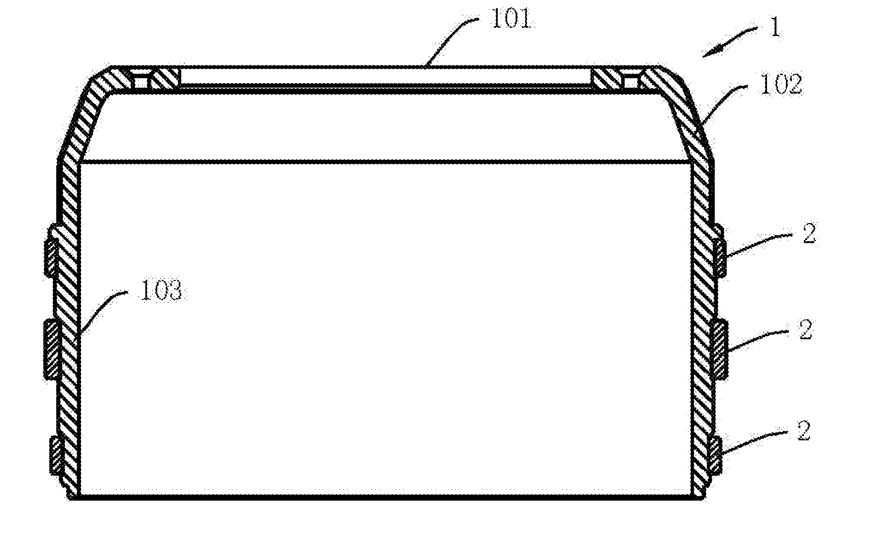
[0050]As shown in FIG. 1, a brake drum, comprising: a brake drum body 1 preferably made of cast iron materials, which comprises a mounting portion 101 for connecting a wheel and a brake portion 103 for fitting with a brake shoe; a transitional connecting portion 102 is disposed between the mounting portion 101 and the brake portion 103; a hoop device is tightly mounted to the outer peripheral surface of the brake portion 103, wherein, the hoop device comprises a plurality of (two or more than two) hoop ferrule 2 arranged in the axial direction which is preferably made of steel materials. Via the clasp force of the hoop ferrule 2, on the premise that the thickness of the brake drum body 1 is reduced, the structural strength, heat dissipation property, mechanical property and safety of the brake drum body 1 are increased, and the service life of the brake drum is extended.

[0051]In FIG. 1, the cross section shape of the hoop ferrule 2 is rectangular, and preferably, the cross sectional...

example 2

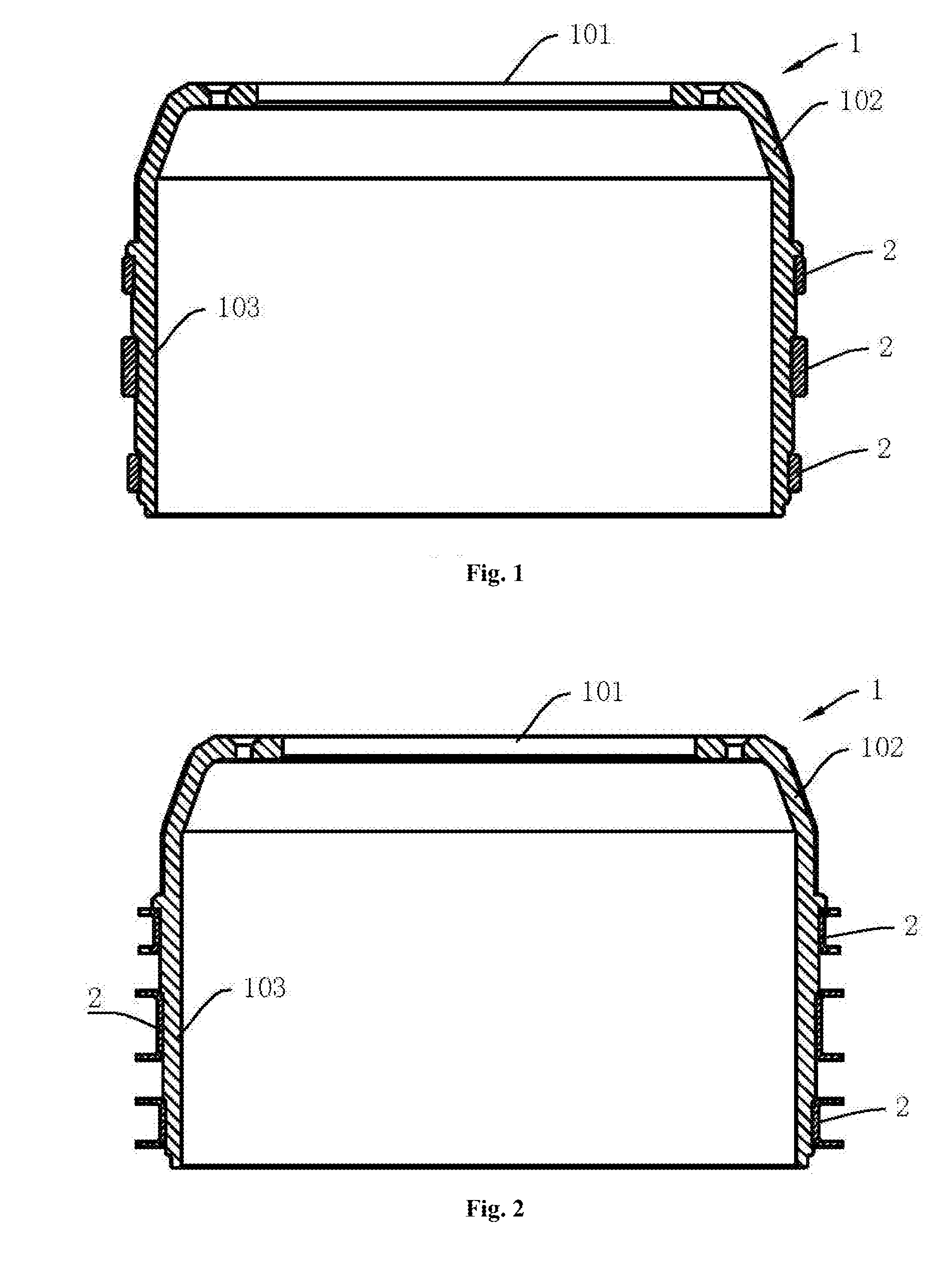
[0052]As shown in FIG. 2, the structure of Example 2 is basically identical with that of Example 1, and the differences are: the cross section shape of the hoop ferrules 2 is U-shaped, which can decrease the thickness of the hoop ferrules 2 and in turn reduce the weight of the hoop ferrules 2 on the premise of ensuring the structural strength of the brake drum body 1.

example 3

[0053]As shown in FIG. 3, the structure of Example 3 is basically identical with that of Example 2, and the differences are: the cross section shape of the hoop ferrules 2 is unequal-height U-shaped; the outer peripheral surface of the brake portion 103 is disposed with a hoop ferrule mounting groove, and all the hoop ferrules 2 abut against each other and are restrainedly mounted in the hoop ferrule mounting groove. The outer peripheral surface of the brake portion 103 is covered with hoop ferrules 2, which can avoid the phenomenon of heat crack and burst of the brake drum body 1 by contacting with water directly when the brake drum body 1 suffers heat and chilling; in addition, the clasp force of the hoop ferrules 2 is much stronger when a plurality of hoop ferrules abut against each other, which avoids the danger of burst and flying out of the brake drum body 1, thereby improving safety, and extending the service life of the brake drum.

[0054]Preferably, the heights of the hoop fe...


PUM

PropertyMeasurementUnit
shapeaaaaaaaaaa
areaaaaaaaaaaa
heightaaaaaaaaaa

Abstract

The present invention discloses a brake drum comprising: a brake drum body, which comprises a mounting portion for connecting a wheel, a braking portion for engagement with a brake shoe, and a transitional connecting portion disposed between the mounting portion and the braking portion; a hoop device is tightly mounted to the outer peripheral surface of the brake portion. The hoop device adopts a plurality of split-type hoop ferrules, or one unibody hollowed-out hoop case. The hoop device tightly mounted to the outer peripheral surface of the brake portion can not only effectively restrain the radial expansion deformation, thereby improving the fatigue resistance of the brake drum body, but also applies a clasp force to the brake drum body, thereby avoiding the danger of burst and flying out of the brake drum body, which greatly improves service life and safety. Moreover, the thickness of the brake portion wall corresponding to the hoop device can be effectively reduced, which not only effectively decreases the temperature difference between the interior and exterior of the brake drum body, but also increases heat conductivity, thereby laying foundation for both heat dissipation and prevention of the happening of the multiple cracks in the inner wall of the brake drum body.

Description

STATEMENT[0001]The present invention claims the priority of the following three patent applications: Chinese invention patent application titled “Circular groove steel hoop brake drum”, of which the application date is Sep. 1, 2014 and the application number is 201410439863.9.[0002]Chinese utility model patent application titled “A brake drum”, of which the application date is Mar. 26, 2015, and the application number is 201520175568.7.[0003]Chinese utility model patent application titled “Brake drum”, of which the application date is Apr. 29, 2015, and the application number is 201520270335.5.TECHNICAL FIELD[0004]The present invention belongs to the technical field of drum-typed brake for using in vehicles, especially relates to a brake drum.BACKGROUND ART[0005]Drum-typed brake is one of the important systems of vehicles and is a brake system applied in vehicles at the earliest time. Its greatest advantage lies in that it is simple in structure and economical in cost, but it can pr...

Claims


Application Information

Patent Timeline
Patent Type & Authority Applications(United States)
IPC IPC(8): F16D65/12B23P11/02
CPCF16D65/12B23P11/025F16D2065/1332F16D65/10
Inventor PU, GUANGMINGLV, JIXIAN
Owner SHANDONG HAOXIN MACHINERY
Why Eureka
Try Eureka