
Continuous flow steam generator with a two-pass boiler design

a technology of continuous flow and steam generator, which is applied in the direction of steam boiler components, steam boilers, water circulation, etc., can solve the problems of inadmissible high temperature, achieve the effect of improving cooling action, increasing mass flow density in steam generator tubes, and increasing mass flow density

Active Publication Date: 2016-06-23
SIEMENS ENERGY GLOBAL GMBH & CO KG
View PDF3 Cites 4 Cited by
  • Summary
  • Abstract
  • Description
  • Claims
  • Application Information

AI Technical Summary

Benefits of technology

The invention proposes a new connection configuration for steam generator tubes in two-pass boilers designed as horizontal gas pass. This configuration allows for an increase in mass flow density and a more even temperature distribution, improving the cooling action and operational reliability. By mixing the flow medium from parallel heating surface segments of two walls, the mass flow density is increased and the temperature rise is reduced. This results in improved cooling at the enclosure walls and reduced heat supply to the heating surface segments, leading to increased homogenization of the inlet temperatures and better operational reliability. Complete mixing is achieved downstream of the outlet collectors, eliminating temperature imbalances and reducing maximum outlet temperatures.

Problems solved by technology

Since heating imbalances however also exist in the steam generator tubes of the upper section, local temperature differences of the flow medium in the steam generator tubes can intensify further within the enclosure walls, and can thus under some circumstances reach inadmissibly high values.

Method used


Image

  • Continuous flow steam generator with a two-pass boiler design
  • Continuous flow steam generator with a two-pass boiler design

Examples


Embodiment Construction

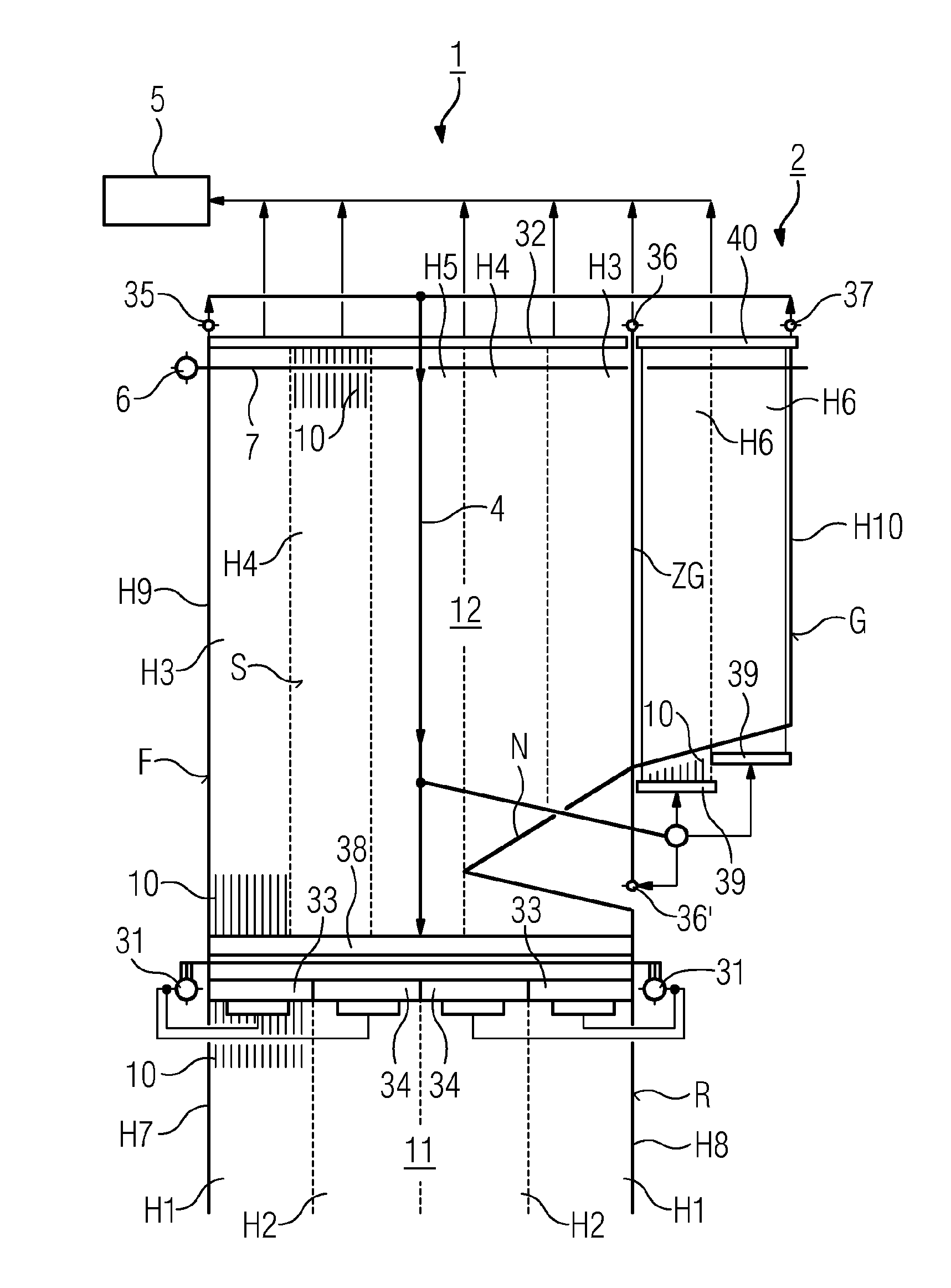
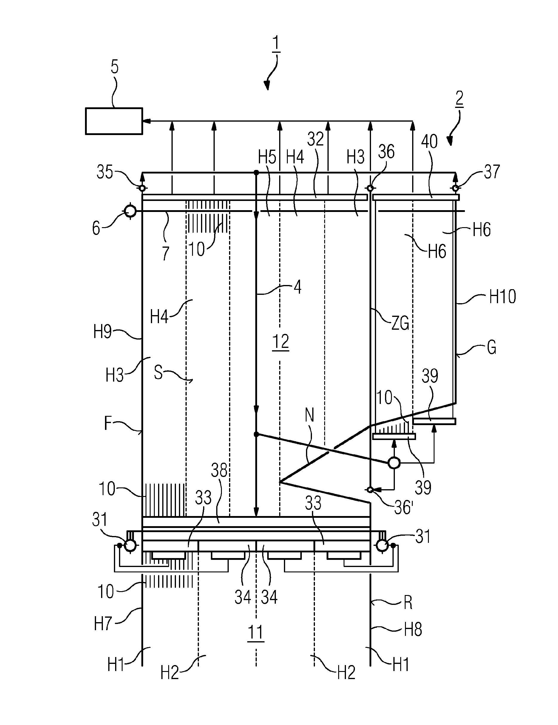
[0014]The invention will now be discussed by way of example on the basis of a figure. Here, the figure schematically illustrates a side view of a possible exemplary embodiment of the continuous flow steam generator according to the invention. The continuous flow steam generator comprises a combustion chamber 1 with a lower combustion chamber region 11 and an upper combustion chamber region 12, wherein a horizontal gas pass 2 adjoins the upper combustion chamber region 12. The horizontal gas pass may then be adjoined by a vertical gas pass that is not illustrated further. A number of burners (not shown in any more detail) are provided in the lower combustion chamber region 11, which burners effect combustion of a liquid, solid or gaseous fuel in the combustion chamber 1. The flue gas generated by the combustion then flows into the upper combustion chamber region 12, and from there into the horizontal gas pass 2. The enclosure walls of the combustion chamber and of the horizontal gas ...


PUM


Abstract

A continuous flow steam generator includes a combustion chamber, having substantially rectangular cross-section and a lower and upper combustion chamber region, and has a horizontal gas pass connected downstream of the combustion chamber on the flue-gas side. Gas-tight and gas-permeable peripheral walls of the generator are completely or partly made of steam generator pipes welded together and through which a flow medium can flow, and collectors are arranged and connected to the steam generator pipes such that groups of steam generator pipes connected in parallel form heating surface segments of the peripheral walls. First passage collectors are arranged and connected such that the flow medium from first heating surface segments of two parallel first peripheral walls of the lower combustion chamber region are mixed with the fluid medium from second heating surface segments of second peripheral walls, standing perpendicular to the first peripheral walls, of the upper combustion chamber region.

Description

CROSS REFERENCE TO RELATED APPLICATIONS[0001]This application is the US National Stage of International Application No. PCT / EP2014 / 066062 filed Jul. 25, 2014, and claims the benefit thereof. The International Application claims the benefit of German Application No. DE 102013215457.7 filed Aug. 6, 2013. All of the applications are incorporated by reference herein in their entirety.FIELD OF INVENTION[0002]The invention relates to a continuous flow steam generator. The invention relates specifically to continuous flow steam generators for power plants, having a combustion chamber which is of substantially rectangular cross section, and having a horizontal gas pass which is connected downstream of the combustion chamber at the flue gas side and which may be adjoined by a further vertical gas pass.BACKGROUND OF INVENTION[0003]Such a construction, also referred to as a two-pass boiler, is known for example from EP 2 182 278 A1. Here, welded-together steam generator tubes through which a f...

Claims


Application Information

Patent Timeline
Patent Type & Authority Applications(United States)
IPC IPC(8): F22B21/34F22B29/06
CPCF22B29/062F22B21/34F22B21/345F22B29/06
Inventor BRODESSER, JOACHIMEFFERT, MARTINSCHULZE, TOBIAS
Owner SIEMENS ENERGY GLOBAL GMBH & CO KG
Learn More