
Method in a communication network

a communication network and communication network technology, applied in the field of communication network systems, can solve the problems of not being able to compare disparate, not having the capability of topologically disassociated timing sources, and not being able to achieve the effect of scalable and accurate network wide area networks

Active Publication Date: 2016-06-16
NET INSIGHT
View PDF4 Cites 14 Cited by
  • Summary
  • Abstract
  • Description
  • Claims
  • Application Information

AI Technical Summary

Benefits of technology

The patent describes a method for validating a network by comparing time information between neighboring nodes. The method can be performed using external sources or interfaces on the first node, making the network more secure. The method also utilizes transmitting and receiving interfaces for two-way time transfer, allowing for comparison of time between nodes and the identification of sources or paths that provide bad timing. Combining local and distributed time measurement data from neighboring nodes can provide a more accurate network-wide comparison of timing sources and paths.

Problems solved by technology

New network technologies for precise timing, including IEEE 1588, have proven to provide sufficient absolute time clocking for large area networks, LAN, and metro deployments, but have not proven to be scalable and accurate for wide area networks, WAN, and do not have the capability of comparing disparate, topologically disassociated timing sources, which in some circumstances is required to detect a faulty clock.
Also, it has been demonstrated that vulnerabilities of these technologies leave networks open to cyber attacks, such as GPS clock jamming and spoofing.

Method used


Image

  • Method in a communication network
  • Method in a communication network
  • Method in a communication network

Examples


Embodiment Construction

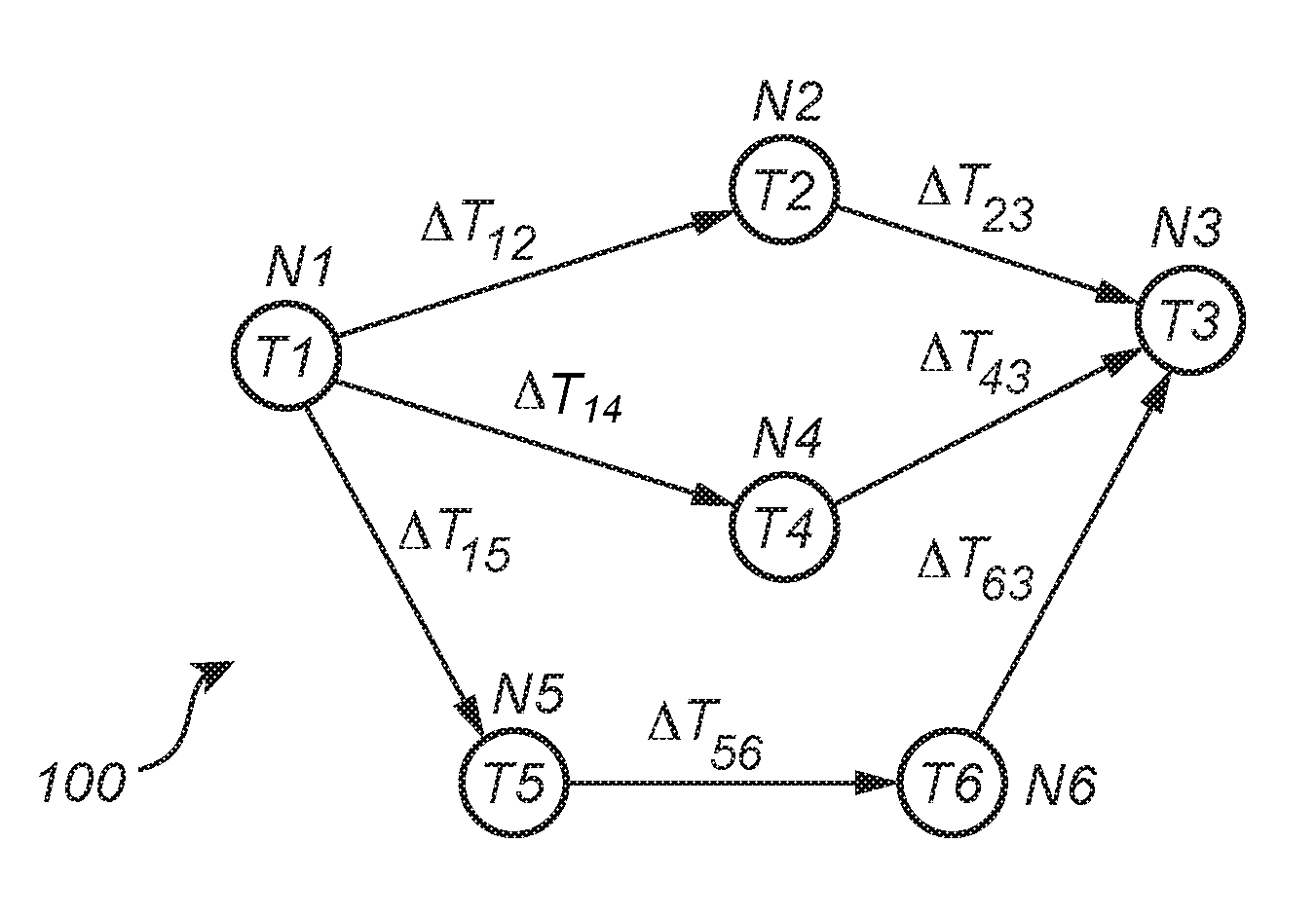
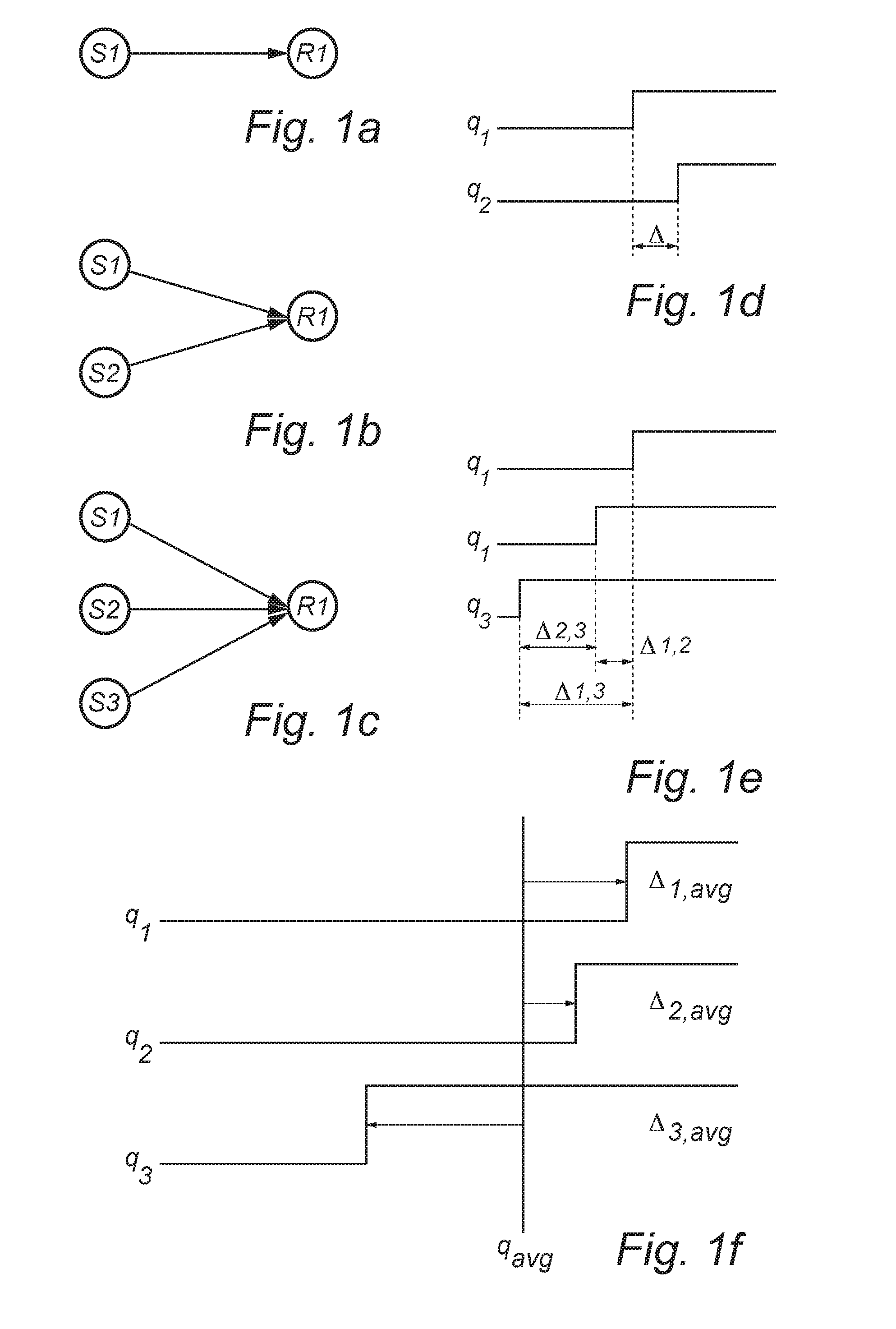
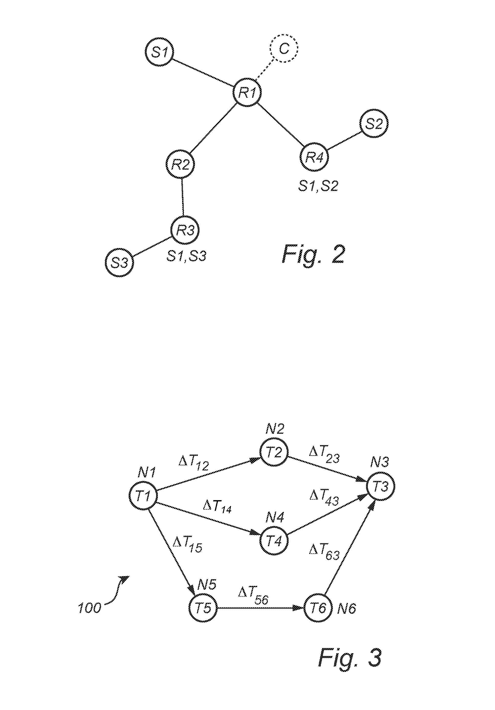
[0028]In an exemplifying embodiment of the present inventive concept, a DTSV method is employed in a two-way transfer communication network system (not shown) comprising nodes capable of two-way time-transfer with node-to-node transmission of data packets. Each node comprises a local clock, at least one network interface capable of transmitting node clock information, and receiving clock information to and from neighboring nodes. Each node is arranged to steer its clock from a selected network interface or another non-network interface. Further, each node is able to convey its clock information on a non-network interface using the transmitting- and receiving network interface in a two-way time-transfer means between two neighbor nodes. Between neighboring nodes, this allows comparison of time, round-trip time between nodes, time or frequency on interface to node with node time, and allows for reporting, i.e. distributing, time or frequency differences between nodes. Thereby the capa...


PUM


Abstract

A method to provide a cyber attack resistant and fault tolerant precision clocking scheme for wide area critical infrastructure networks through what is called Distributed Time Source Validation, DTSV, is provided, which is a distributed algorithm and signaling mechanism for a network to detect a compromised time source or sources in a multiple master clock system. The method includes providing a local clock signal, receiving in a node R1 an external clock signal from an external source, C or S1, estimating based on the local clock signal and the external clock signal timing parameters associated with the first node and the external source, comparing the timing parameters to detect any Mutual Clock Discrepancy (MCD) between the first node and the external source, and distributing any detected MCD in the network.

Description

PRIORITY STATEMENT[0001]The present application hereby claims priority under 35 U.S.C. §119 to Swedish patent application number SE 1451533-2 filed Dec. 12, 2014, the entire contents of which are hereby incorporated herein by reference.TECHNICAL FIELD[0002]The present invention relates to the field of communication network system for node-to-node transmission of data, and more particularly to a method for providing time source validation in a distributed network with multiple sources and multiple paths.BACKGROUND OF THE INVENTION[0003]In recent years, substantial attention has been directed to real time communication over packet switched communication networks like the Internet. In real time communication, such as audio and video streaming, timeliness and low latency can be more important than reliability of the packet streaming / transport. New network technologies for precise timing, including IEEE 1588, have proven to provide sufficient absolute time clocking for large area network...

Claims


Application Information

Patent Timeline
IPC IPC(8): H04L12/26H04L29/06H04L12/24
CPCH04L43/0864H04L63/1408H04L41/064H04J3/0641H04J3/0644H04J3/0676H04J3/0682H04J3/14
Inventor DANIELSSON, MAGNUS
Owner NET INSIGHT
Learn More