Eureka AIR delivers breakthrough ideas for toughest innovation challenges, trusted by R&D personnel around the world.

Method for a first network node for transmitting or retransmitting data to a second network node and first network node thereof and method for a second network node for receiving data transmitted or retransmitted from a first network node and second network node thereof

a network node and data technology, applied in the field of retransmission and network coding, can solve the problems of significant throughput degradation, throughput performance, and the inability of the second transceiver apparatus to recover error-free data packets, and achieve the effect of reducing the feedback overhead of retransmission

Active Publication Date: 2016-06-16
ALCATEL LUCENT SAS
View PDF9 Cites 18 Cited by
  • Summary
  • Abstract
  • Description
  • Claims
  • Application Information

AI Technical Summary

Benefits of technology

The invention aims to improve wireless communication by reducing the feedback required for retransmissions. This is achieved by segmenting data packets into two parts and providing alternative feedback parameters for each segment. This reduces the amount of feedback information needed in case of multiple data segmentations. Overall, this improves data transmission efficiency and reduces the burden on the network.

Problems solved by technology

When a data volume such as a data packet is transmitted initially by radio frequency signals from a first transceiver apparatus via a transmission channel such as a wireless transmission channel to a second transceiver apparatus, several effects such as scattering, fading and / or power decay usually have an impact on the transmitted signal at a location of the second transceiver apparatus and therefore, modified radio frequency signals or in a worst case no radio frequency signals are received by the second transceiver apparatus so that the second transceiver apparatus may not be able to recover error-free the data packet by a single transmission.
Imperfect link adaptation causes significant throughput degradation as compared to the theoretical limits, despite of using HARQ.
Throughput performance is a critical issue in wireless communication, because a radio link is usually a bottleneck for a transmission of data from a base station to a mobile station or backwards.

Method used


Image

  • Method for a first network node for transmitting or retransmitting data to a second network node and first network node thereof and method for a second network node for receiving data transmitted or retransmitted from a first network node and second network node thereof
  • Method for a first network node for transmitting or retransmitting data to a second network node and first network node thereof and method for a second network node for receiving data transmitted or retransmitted from a first network node and second network node thereof
  • Method for a first network node for transmitting or retransmitting data to a second network node and first network node thereof and method for a second network node for receiving data transmitted or retransmitted from a first network node and second network node thereof

Examples


Embodiment Construction

[0047]The description and drawings merely illustrate the principles of the invention. It will thus be appreciated that those skilled in the art will be able to devise various arrangements that, although not explicitly described or shown herein, embody the principles of the invention and are included within its spirit and scope. Furthermore, all examples recited herein are principally intended expressly to be only for pedagogical purposes to aid the reader in understanding the principles of the invention and the concepts contributed by the inventors to furthering the art, and are to be construed as being without limitation to such specifically recited examples and conditions. Moreover, all statements herein reciting principles, aspects, and embodiments of the invention, as well as specific examples thereof, are intended to encompass equivalents thereof.

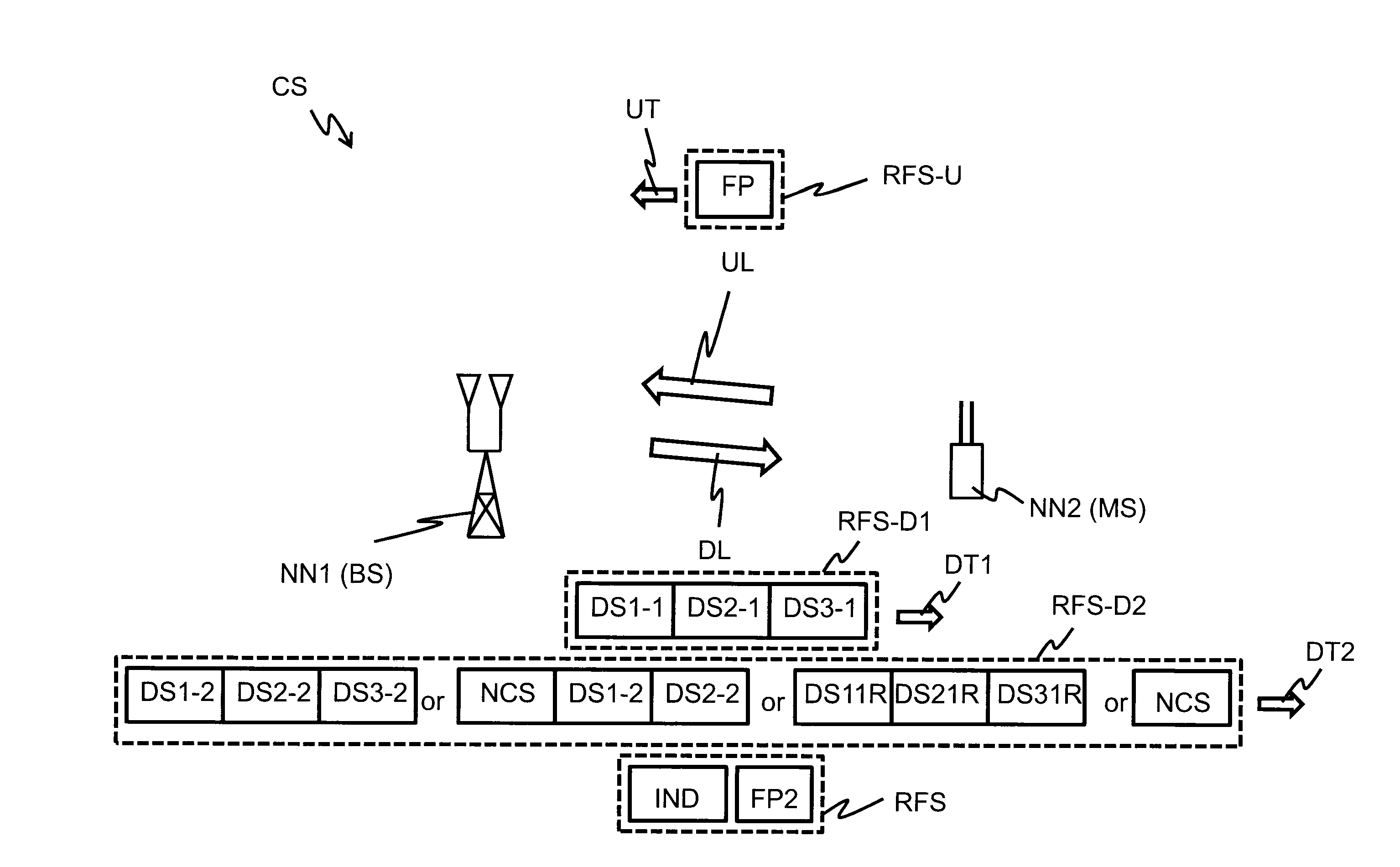
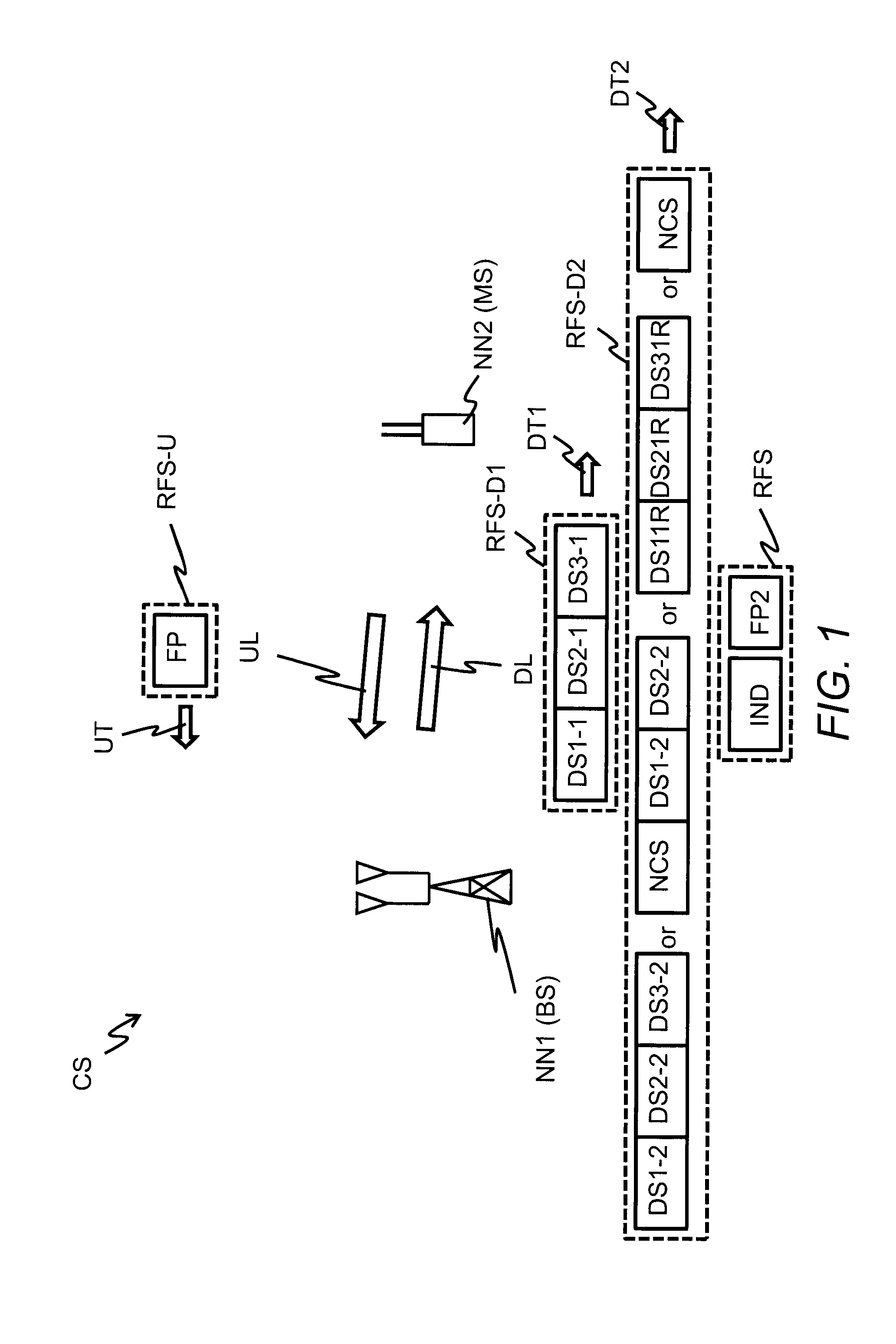
[0048]FIG. 1 shows schematically a block diagram of a communication system CS, which contains a first network node NN1 in communicati...


PUM


Abstract

The embodiments of the invention relate to a method for a first network node (NN1) for transmitting or retransmitting data to a second network node (NN2). The method contains receiving at the first network node (NN1) from the second network node (NN2) a feedback parameter (FP) in response to a first transmission (DT1) of at least two data segments (DS1-1, DS2-1, DS3-1) of a data packet. The feedback parameter (FP) is a number of counted data segments of the at least two data segments (DS1-1, DS2-1, DS3-1) incorrectly received or lost or correctly received at the second network node (NN2) by the first transmission (DT1). The method further contains determining at the first network node (NN1) for a second transmission (DT2) to the second network node (NN2) the data (DS1-2, DS2-2, DS3-2, NCS, DS1 1 R, DS21 R, DS31 R) as a function of the feedback parameter (FP) and transmitting or retransmitting the data (DS1-2, DS2-2, DS3-2, NCS, DS1 1 R, DS21 R, DS31 R) by the second transmission (DT2) from the first network node (NN1) to the second network node (NN2). The embodiments of the invention further relate to a further method for the second network node (NN2) for receiving data transmitted or retransmitted from the first network node (NN1). The further method (MET-NN2) contains determining at the second network node (NN2) the feedback parameter (FP) in response to the first transmission (DT1) from the first network node (NN1) to the second network node (NN2), transmitting from the second network node (NN2) the feedback parameter (FP) to the first network node (NN1), and receiving at the second network node (NN2) the data (DS1-2, DS2-2, DS3-2, NCS, DS1 1 R, DS21 R, DS31 R) by the second transmission (DT2) from the first network node (NN1). The embodiments of the invention further relate to a first computer program, the first network node (NN1), a second computer program and to the second network node (NN2).

Description

FIELD OF THE INVENTION[0001]The present invention relates to transmission and retransmission of data in a communication system and, more particularly but not exclusively, to retransmission and network coding in a radio communication system.BACKGROUND OF THE INVENTION[0002]This section introduces aspects that may be helpful in facilitating a better understanding of the invention. Accordingly, the statements of this section are to be read in this light and are not to be understood as admission about what is in the prior art.[0003]When a data volume such as a data packet is transmitted initially by radio frequency signals from a first transceiver apparatus via a transmission channel such as a wireless transmission channel to a second transceiver apparatus, several effects such as scattering, fading and / or power decay usually have an impact on the transmitted signal at a location of the second transceiver apparatus and therefore, modified radio frequency signals or in a worst case no ra...

Claims


Application Information

Patent Timeline
IPC IPC(8): H04L1/18H04L1/00
CPCH04L1/0076H04L1/1819H04L1/0056H04L1/0057H04L1/0075H04L1/1607H04L1/1896
Inventor BRAUN, VOLKERDOETSCH, UWE
Owner ALCATEL LUCENT SAS
Why Eureka
Eureka Blog
Learn More