
System and Method for Channel Status Information Feedback in a Wireless Communications System

a wireless communication system and status information technology, applied in the field of wireless communications, can solve the problems of wireless communications system not being able to operate at maximum efficiency, feedback mechanisms usually have higher overhead than channel reciprocity, and transmitter antennas are generally more expensive to implement, so as to reduce feedback overhead, reduce the size of a codebook, and reduce the dimension of quantized channels

Active Publication Date: 2009-10-15
FUTUREWEI TECH INC
View PDF9 Cites 27 Cited by
  • Summary
  • Abstract
  • Description
  • Claims
  • Application Information

AI Technical Summary

Benefits of technology

The patent text describes a system and method for determining channel state information in a wireless communications system. The technical effects of the invention include using both quantized channel feedback and channel reciprocity to obtain full CSI even in situations where there are fewer transmit antennas than receive / transmit antennas. This reduces the size of the codebook used for quantized channel information feedback and decreases storage requirements. Additionally, the invention allows for a smaller codebook to reduce feedback overhead and decrease storage requirements.

Problems solved by technology

This is due to the fact that transmitter antennas are generally more expensive to implement due to their costly power amplifiers, for example.
Therefore, the BS does not have full CSI and the wireless communications system may not be able to operate at maximum efficiency.
However, such feedback mechanisms usually have higher overhead than channel reciprocity.
However, since the BS can identify only a portion of the channel information, the transmission efficiency of the BS may be lower than what is achievable with full channel information.
However, this technique may require a significant amount of time to elapse before the BS can have CSI for all K×N channel elements (i.e., it may take longer to acquire the full CSI because the MS has to report CSI to the BS multiple times).
This technique may also require the addition of switching logic at the MS, which will increase the cost of the MS.

Method used


Image

  • System and Method for Channel Status Information Feedback in a Wireless Communications System
  • System and Method for Channel Status Information Feedback in a Wireless Communications System
  • System and Method for Channel Status Information Feedback in a Wireless Communications System

Examples


Embodiment Construction

[0027]The making and using of the embodiments are discussed in detail below. It should be appreciated, however, that the present invention provides many applicable inventive concepts that can be embodied in a wide variety of specific contexts. The specific embodiments discussed are merely illustrative of specific ways to make and use the invention, and do not limit the scope of the invention.

[0028]The embodiments will be described in a specific context, namely a wireless communications system operating in TDD mode. The invention may also be applied to a variety of wireless communications system transmission mechanisms, such as orthogonal frequency division multiple access (OFDMA), code division multiple access (CDMA), time division multiple access (TDMA), frequency division multiple access (FDMA), spatial division multiple access (SDMA), and so on.

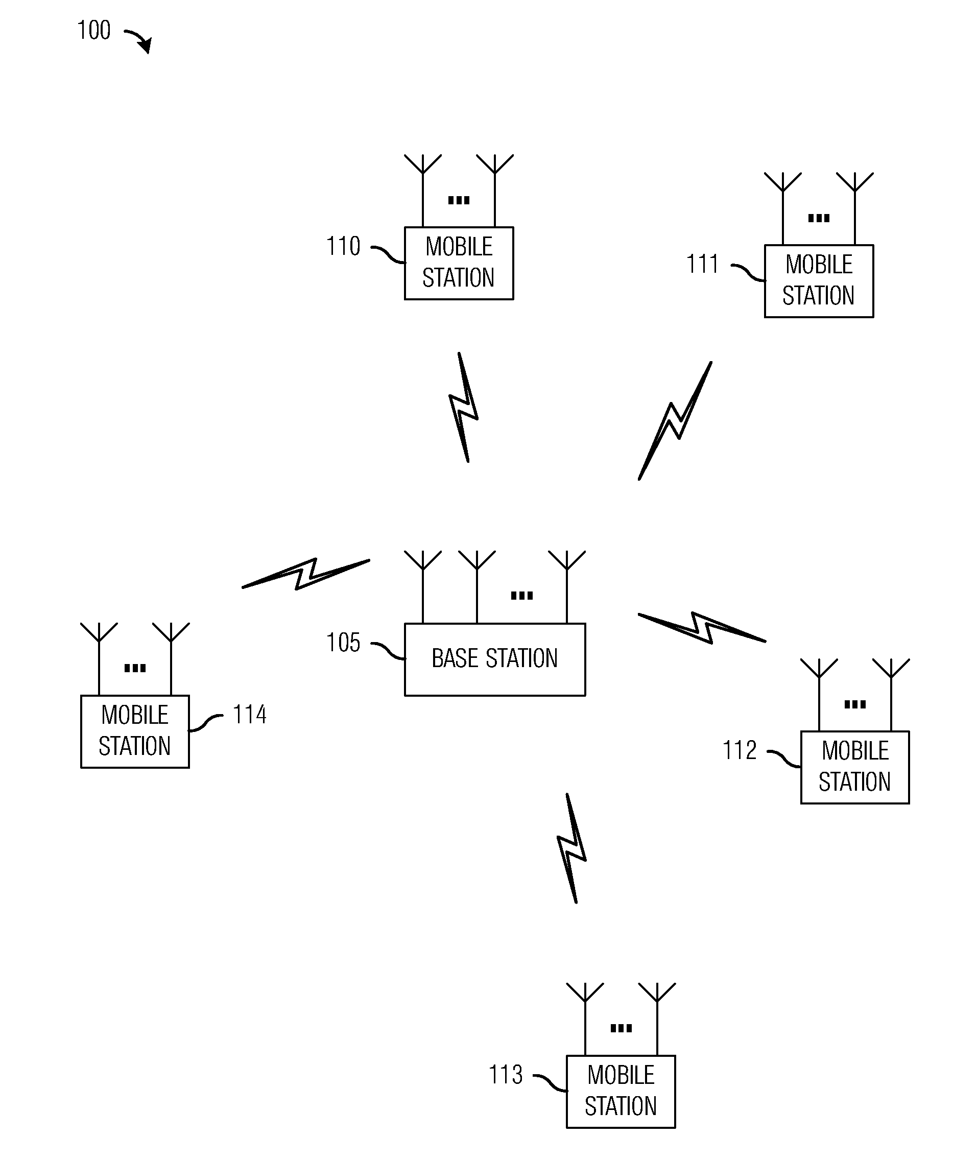
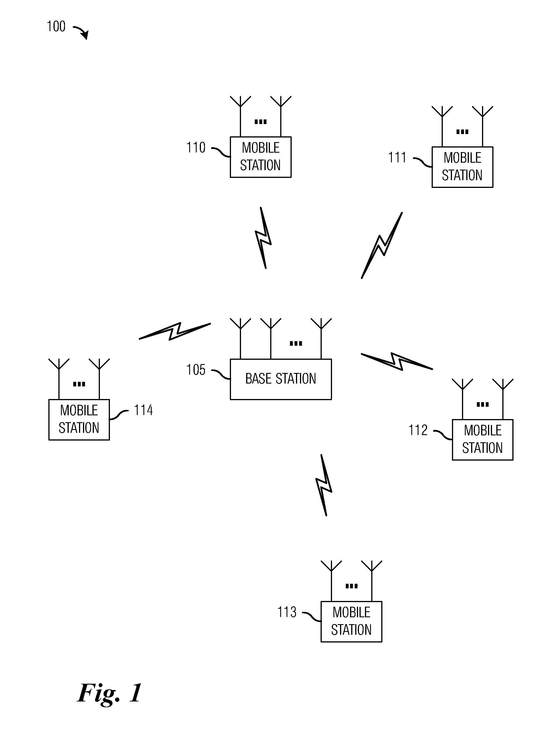
[0029]FIG. 1 illustrates a wireless communications system 100. Wireless communications system 100 includes a base station (BS) 105. BS 10...


PUM


Abstract

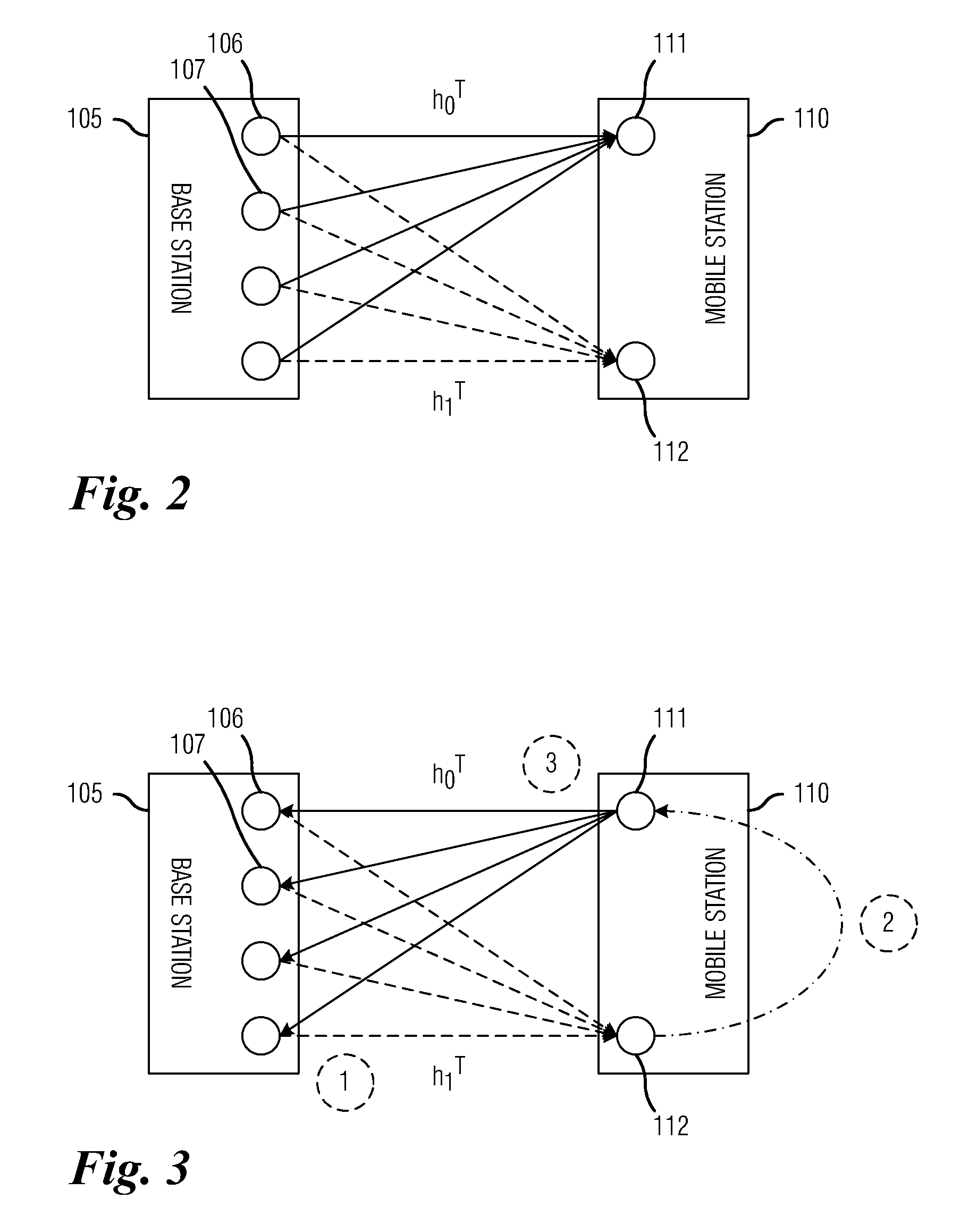
A system and method for channel status information feedback in a wireless communications system is provided. A method includes receiving a transmission containing feedback information from a mobile station (MS) having N total antennas, M receive / transmit antennas, N−M receive-only antennas, wherein N and M are integers and N>M, decoding the received transmission, computing estimates of CSI for channel elements of N−M receive-only antennas using the decoded transmission, computing estimates of CSI for channel elements of M receive / transmit antennas using channel reciprocity, and computing a precoding matrix from the channel elements for the N−M receive-only antennas and the M receive / transmit antennas.

Description

[0001]This application claims the benefit of U.S. Provisional Application No. 61 / 044,792, filed on Apr. 14, 2008, entitled “Method and an Apparatus for Channel Status Information Feedback for MIMO Precoding in TDD Mode,” which application is hereby incorporated herein by reference.TECHNICAL FIELD[0002]The present invention relates generally to wireless communications, and more particularly to a system and method for channel status information feedback in a wireless communications system.BACKGROUND[0003]In order to achieve better channel utilization and increase overall performance, multiple transmission and multiple reception antennas (also commonly referred to as multiple input, multiple output (MIMO)) at both base station (BS) and mobile station (MS) are considered.[0004]Generally, to have better spectral efficiency, a transmitter in a MIMO system needs to know channel status information (CSI) of channels between transmitter and receiver antennas. To this end, several CSI feedback...

Claims


Application Information

Patent Timeline
Patent Type & Authority Applications(United States)
IPC IPC(8): H04B7/00H04J3/00
CPCH04B7/0626
Inventor KWON, YOUNG HOONTANG, YANGWU, TAO
Owner FUTUREWEI TECH INC
Learn More