
Gas injectors

Inactive Publication Date: 2016-06-16
SAMSUNG ELECTRONICS CO LTD
View PDF2 Cites 86 Cited by
  • Summary
  • Abstract
  • Description
  • Claims
  • Application Information

AI Technical Summary

Benefits of technology

The patent text describes how increasing the height of ejection holes in a gas introduction tube can affect the distance between adjacent holes. In some cases, increasing the height can lead to a decrease in the distance between the holes, while in other cases, it can lead to an increase in the size of the holes. Overall, the technical effect of the patent is how to optimize the design of gas introduction systems for industrial applications.

Problems solved by technology

Accordingly, a pressure difference and an ejection velocity difference between upper and lower portions of the gas injector may be relatively great, so that a process variation may be deteriorated.

Method used


Image

  • Gas injectors
  • Gas injectors
  • Gas injectors

Examples


Embodiment Construction

[0063]Example embodiments will now be described more fully with reference to the accompanying drawings. Embodiments, however, may be embodied in many different forms and should not be construed as being limited to the embodiments set forth herein. Rather, these example embodiments are provided so that this disclosure will be thorough and complete, and will fully convey the scope to those skilled in the art. In the drawings, the thicknesses of layers and regions may be exaggerated for clarity.

[0064]It will be understood that when an element is referred to as being “on,”“connected to,”“electrically connected to,” or “coupled to” to another component, it may be directly on, connected to, electrically connected to, or coupled to the other component or intervening components may be present. In contrast, when a component is referred to as being “directly on,”“directly connected to,”“directly electrically connected to,” or “directly coupled to” another component, there are no intervening c...


PUM

PropertyMeasurementUnit
Sizeaaaaaaaaaa
Shapeaaaaaaaaaa
Radiusaaaaaaaaaa

Abstract

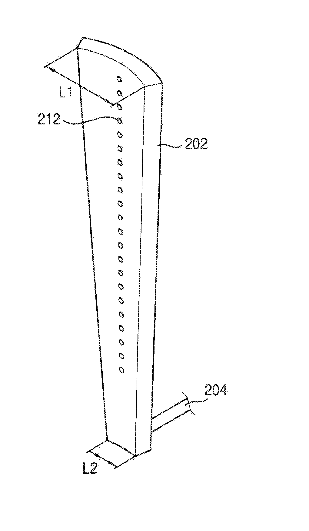
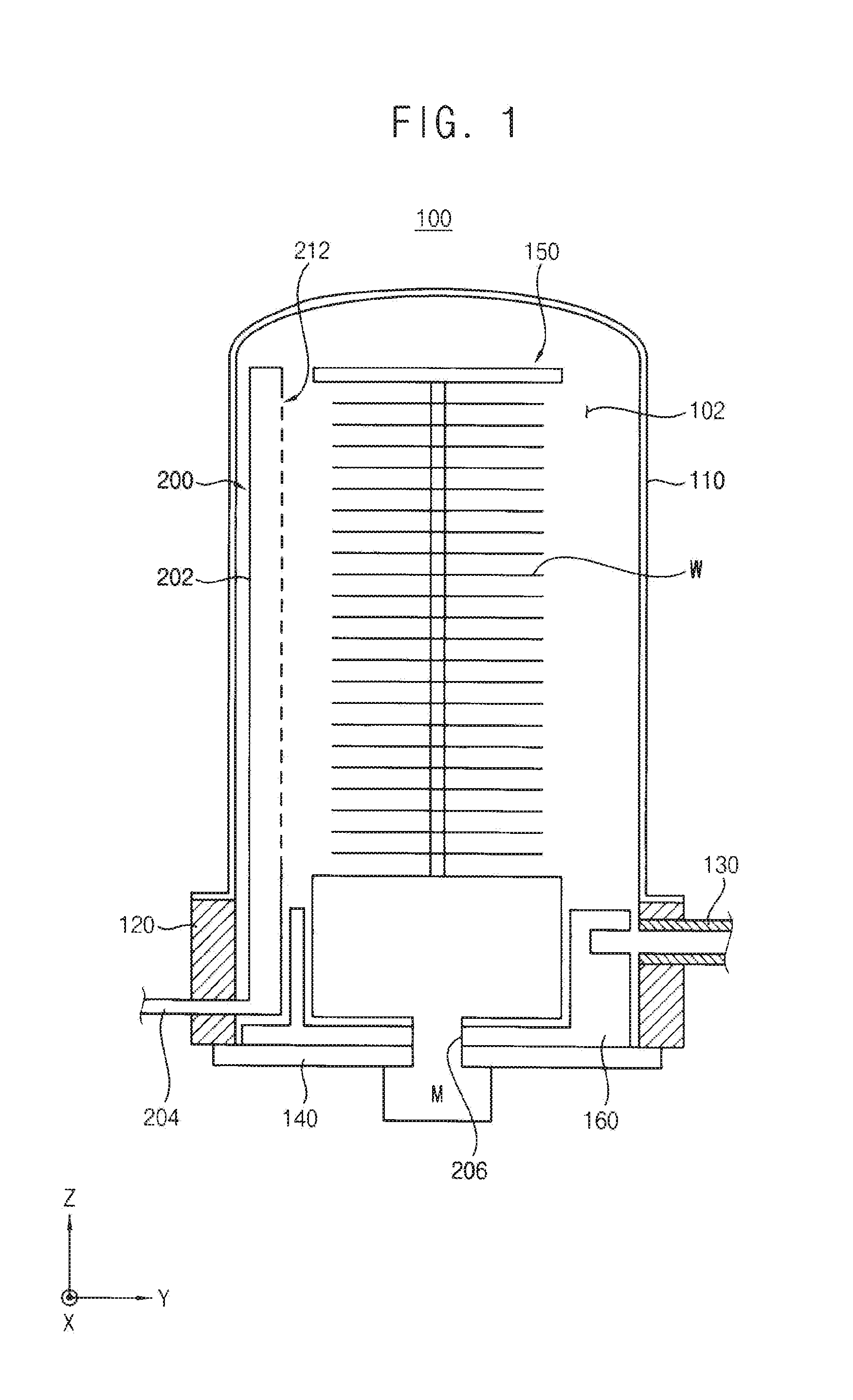
A gas injector may comprise: a gas introduction tube configured to introduce reaction gas into a reaction tube from a gas supply source; and / or a gas distributor connected to the gas introduction tube, extending from the gas introduction tube in a direction within the reaction tube, including a plurality of ejection holes in an inner surface of the gas distributor, and having an arc shape extending in a circumferential direction of the reaction tube. The ejection holes may be spaced apart from each other in the extending direction of the gas distributor, and are configured to spray the reaction gas.

Description

CROSS-REFERENCE TO RELATED APPLICATION(S)[0001]This application claims priority from Korean Patent Application No. 10-2014-0177175, filed on Dec. 10, 2014, in the Korean Intellectual Property Office (KIPO), the entire contents of which are incorporated herein by reference.BACKGROUND[0002]1. Field[0003]Some example embodiments may relate generally to gas injectors. Some example embodiments may relate generally to wafer processing apparatuses having gas injectors. Some example embodiments may relate generally to gas injectors supplying process gases into process chambers. Some example embodiments may relate generally to wafer processing apparatuses having such gas injectors.[0004]2. Description of Related Art[0005]A plurality of vertically stacked wafers may be loaded into a batch reactor and then an atomic layer deposition (ALD) process may be performed to form a layer on the wafers. Especially, a blocking layer, a charge storage layer, and a tunnel insulation layer of a cell transis...

Claims


Application Information

Patent Timeline
IPC IPC(8): C23C16/455
CPCC23C16/45544C23C16/45563C23C16/45546C23C16/45578H01L21/0262H01L21/02532
Inventor CHOI, JI-HOONNOH, YOUNG-JINRA, JOONG-YUNAHN, JAE-YOUNGLIM, HUN-HYEONG
Owner SAMSUNG ELECTRONICS CO LTD
Learn More