
Bioreactor consumable units

Active Publication Date: 2016-06-02
THE AUTOMATION PARTNERSHIP CAMBRIDGE
View PDF5 Cites 19 Cited by
  • Summary
  • Abstract
  • Description
  • Claims
  • Application Information

AI Technical Summary

Benefits of technology

This patent describes a bioreactor system that is easy to set up and operate. The system includes a bioreactor consumable unit that has a connection between the fluid feed container and the bioreactor, as well as a pumping element (the syringe and valve). This eliminates the need to make separate fluid connections between the bioreactor chamber and the fluid feed container. The pumping element is integrated with the consumable unit, so there is no need for separate fluids connections to the pump. When the system is ready to use, the pump automatically connects and is ready for operation. Syringe designs have a small fluid volume between the syringe and the fluid feed container, which prevents air bubbles from entering the pumping system. This setup prevents air / liquid mixtures from being pumped to the bioreactor.

Problems solved by technology

Such issues become significant in very large bioreactors.
A major challenge facing companies manufacturing products in bioreactor systems is the optimisation of the conditions within a bioreactor for the production of a particular product.
Addressing this issue is not simple; there are many parameters to be controlled and the optimal approach may involve variations in these conditions over time.
However, it is impractical to explore the impact of varying a range of parameters due to the lack of availability of equipment and the huge costs of operation.
At larger scales the cost rapidly becomes prohibitive.
Such issues prevent the application of modern statistical based experiment approaches to resolving the impact of multiple parameter variation typically referred to as DOE (Design of Experiment), such approaches typically requiring tens of bioreactor experiments to have value.
A further issue faced is the difficulty of selecting cell lines early in development that are robust and productive in a stirred bioreactor environment.
Clearly, where high tens to hundreds of cell lines need to be screened, existing bioreactor systems are impractical.
A number of small-scale approach bioreactors have been tried, e.g. shaken multiwell plates and flasks, but these lack the ability to faithfully reproduce the conditions found in stirred, gassed systems with closed loop control of culture parameters.
Whereas this simplifies the system, the vessels not requiring individual stirrers, it does not produce accurate simulation of production scale conditions, in which the contents are stirred; shaking does not replicate the shear forces induced in the vessel contents by stirring.
However, above a certain cell density the production of lactic acid by the cells can overwhelm the buffering capability of the media and the pH is maintained within the desired limits by the addition of doses of alkali solutions to combat the increasing acidity.
Some parameters are controlled through closed loop sensing and response systems, others through sampling and off-line analysis due to the lack of appropriate on-line monitoring systems.
It is time-consuming and often manually complex for an operator to connect and disconnect the fluid conduits to the respective inlet / outlet ports so as to establish the multiple fluid pathways for the input of gases and / or nutrients and / or acid, base and anti-foaming agents into the bioreactor.
However, a drawback of this approach is that fluids can remain in the conduits of the clamp plate between experiment runs, risking contamination of subsequent runs—particularly in the case of the nutrient feed.
To perform the operation multiple times, on the various different lines of tubing needed to connect the multiple sources to the bioreactor can be complicated, time-consuming and relatively expensive.
Hence, the pulsatile flow from peristaltic pumps, diaphragm pumps, and reciprocating piston pumps is not ideal.
In summary, there is a range of challenges in the development and optimisation of bioreactor based manufacturing processes, including: i) general costs of operation of current systems, even that of small scale systems being prohibitive due to complexity of set-up, labour, capital cost, equipment availability within facilities infrastructure required (steam generation) and high costs of media components per unit volume; ii) lack of directly applicable small-scale systems to model larger bioreactors; and iii) a lack of trained personnel driving the requirement for improved throughput per trained employee.

Method used


Image

  • Bioreactor consumable units
  • Bioreactor consumable units
  • Bioreactor consumable units

Examples


Embodiment Construction

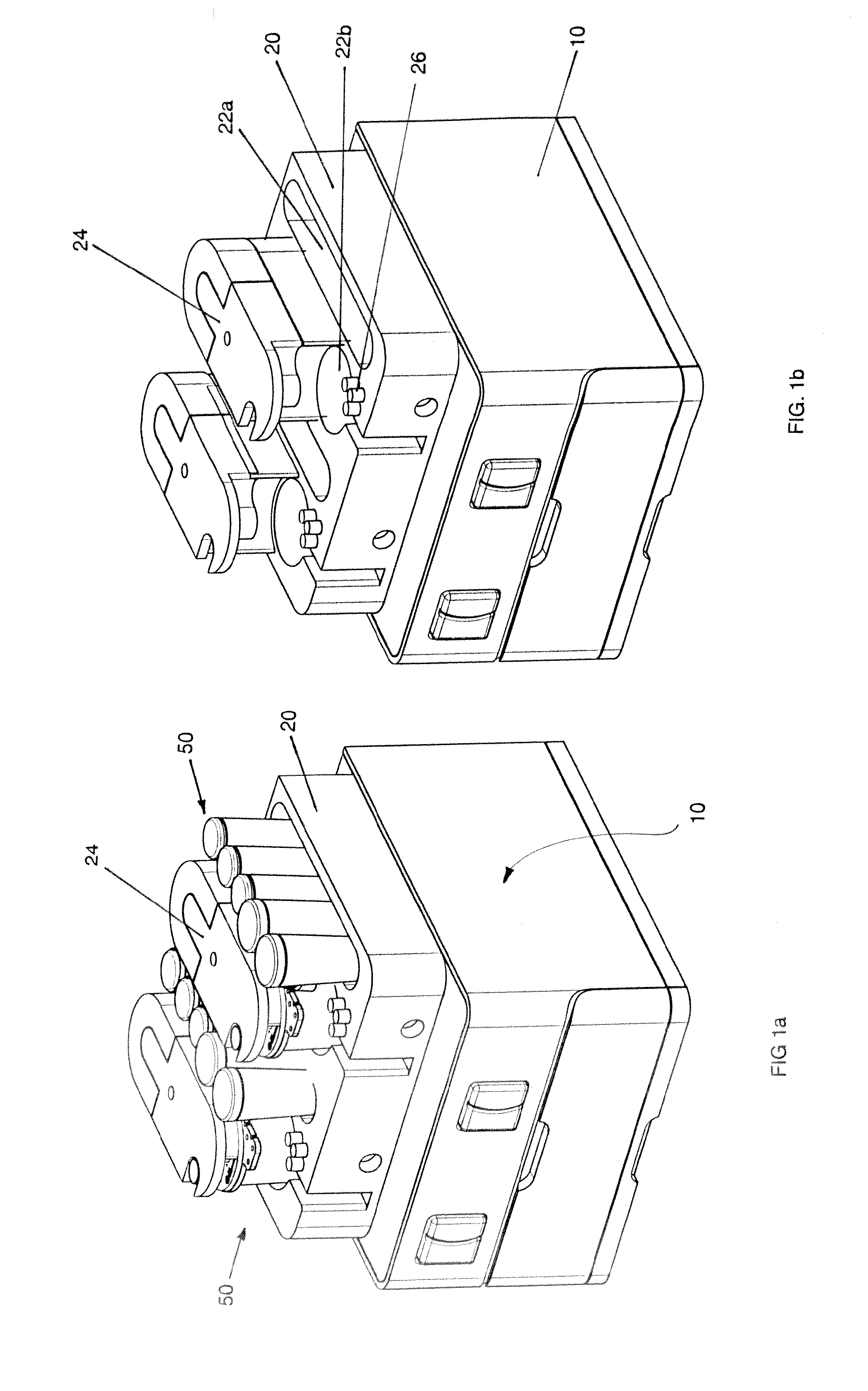
[0093]As shown generally in FIGS. 1a and 1b, a cell culture module 10, comprises, generally, a receiving station 20 for removably receiving one or more bioreactor consumable units (BCUs) 50 under respective clamping lid portions 24. In the illustrated embodiment, the receiving station 20 is adapted to receive a pair of BCUs 50, but it will be appreciated that in other embodiments the receiving station could instead be adapted to receive just one or more than two BCUs 50.

[0094]The module 10 may be operated as a stand-alone unit (as shown in FIG. 1a) or may be interconnected, physically and / or communicatively, to other such modules to form a larger, modular system (not shown). In such a modular system, one of the modules 10 may be a central or ‘head’ module, for centrally controlling at least part of the operation of the other modules in the system, as will be described in greater detail elsewhere.

[0095]One embodiment of a BCU 50 is shown in FIGS. 2 to 4. The BCU 50 comprises a biorea...


PUM


Abstract

A bioreactor consumable unit (50; 500) comprises a bioreactor part (60); a fluid feed container part (80) integrally connected with the bioreactor part and including at least one fluid feed container (82) in fluid communication with the bioreactor (60); and an integral pumping element (100, 110; 160, 206) configured to enable fluid to flow from the at least one fluid feed container (82) to the bioreactor (60). The bioreactor part (60) includes a bioreactor chamber (62) and a stirrer (64) for agitation of a cell culture (66) in the chamber. The pumping element comprises a combination of a syringe pump (110) and an associated three-way valve (102). The bioreactor consumable unit (50; 500) may be inserted into a receiving station (20) of a cell culture module (10) for the processing and control of a bioreaction in the bioreactor chamber (62). The provision of the fluid feed containers (82) and the pumping element (100, 110; 60, 206) as integral parts of the bioreactor consumable unit (50; 500) facilitates the set-up of the processing, because the various fluid connections between those components are already established. The syringe pump (110) provides accurate dispensing of fluids to the bioreactor chamber (62).

Description

FIELD OF THE INVENTION[0001]The invention relates generally to the field of bioreactor processing systems for cell cultures. More particularly, the invention concerns bioreactor consumable units, to improve the handling and set-up of bioreactors and their associated fluid feeds Throughout this document, the term ‘cell culture’ is to be understood as encompassing not only mammalian cell cultures, but also insects, algae, plants and microbial cell cultures (fermentation) and any other cell types, as well as other biochemical or cellular processes such as, but not limited to biotransformations, transfection, transient protein expression, cell-free biological systems. However, this invention could also be used for other, non-biological, processes.BACKGROUND TO THE INVENTION[0002]Cell cultures, consisting of cells growing suspended in a growth media, or on the surface of suspended particles, in solution are produced within bioreactors with careful control of a number of parameters. These...

Claims


Application Information

Patent Timeline
IPC IPC(8): C12M3/00C12M1/26C12M1/12C12M1/34C12M1/00C12M1/06
CPCC12M23/44C12M29/00C12M27/02C12M33/04C12M41/34C12M41/42C12M37/02C12M23/42C12M23/48C12M23/58C12M23/30
Inventor BARGH, ADRIAN NEILSTACEY, ADRIAN JAMESSULLIVAN, SEAN KENNETH
Owner THE AUTOMATION PARTNERSHIP CAMBRIDGE
Learn More