Eureka AIR delivers breakthrough ideas for toughest innovation challenges, trusted by R&D personnel around the world.

Wireless inductive power transfer

a technology of inductive power transfer and wireless, which is applied in the direction of inductance, reradiation, instruments, etc., can solve the problems of inconvenient use, inability to detect, and inability to detect, so as to increase the probability of detection, and reduce the probability of detection

Active Publication Date: 2016-05-26
KONINKLJIJKE PHILIPS NV
View PDF6 Cites 49 Cited by
  • Summary
  • Abstract
  • Description
  • Claims
  • Application Information

AI Technical Summary

Benefits of technology

The invention described in this patent improves performance in various scenarios. It can make things better for users and reduce the risk of unnecessary power transfer interruptions while avoiding unreasonable heating of foreign objects. The amount of user input required to improve parasitic power loss or foreign object detection can be reduced. This invention can efficiently support power receiver operations, providing a highly advantageous solution.

Problems solved by technology

However, this tends to be impractical and requires the user to physically insert connectors or otherwise establish a physical electrical contact.
It also tends to be inconvenient to the user by introducing lengths of wire.
Although, the use of internal batteries may avoid the need for a wired connection to a power supply during use, this only provides a partial solution as the batteries will need recharging (or replacing which is expensive).
The use of batteries may also add substantially to the weight and potentially cost and size of the devices.
However, such a bidirectional link is not trivial to include and is subject to a large number of difficulties and challenges.
Furthermore, the technical restrictions in terms of e.g. modulation options, power variations, transmission options etc. are very restrictive as they need to fit in with the existing parameters.
Accordingly, many challenges and difficulties are associated with enhancing a power transfer system such as Qi to include bidirectional communication.
A potential problem with wireless power transfer is that power may unintentionally be transferred to e.g. metallic objects.
The heat increase may be very significant and may indeed result in a risk of pain and damage to humans subsequently picking up the objects.
For comparison, skin burning caused by contact with hot objects starts at temperatures of around 65° C. The experiments have indicated that a power absorption of 500 mW or more in a typical foreign object rises its temperature to an unacceptable level.
For example, a foreign object may be positioned on or near the power transmitter resulting in this being heated due to the power signal.
It is substantially more difficult to determine the transmitted and received power estimates sufficiently accurately at higher power levels than for lower power levels.
Thus, whereas such accuracy may be acceptable for a low power transfer operation it is not acceptable for a high power transfer operation.
This is particularly difficult at high power levels, and frequently it is difficult for power receivers to generate estimates that are sufficiently accurate.
However, if the power receiver overestimates the received power, this can result in power consumption by foreign objects not being detected.
Conversely, if the power receiver underestimates the received power, this may lead to false detections where the power transmitter terminates the power transfer despite no foreign objects being present.
However, although such an approach may be desirable in many scenarios, it may also be considered inconvenient to the user as such calibrations may at best delay the power transfer, and may in many scenarios require user involvement before power transfer can proceed.

Method used


Image

  • Wireless inductive power transfer
  • Wireless inductive power transfer
  • Wireless inductive power transfer

Examples


Embodiment Construction

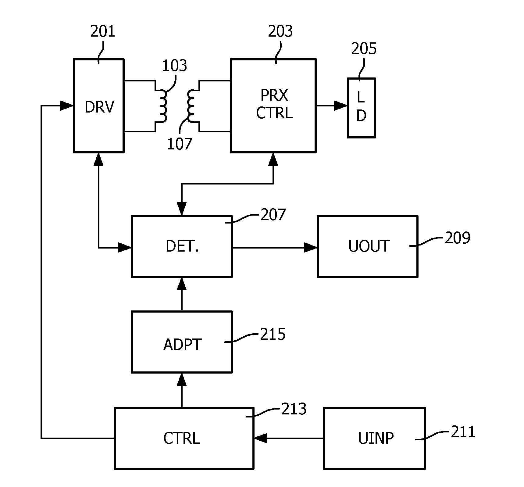
[0166]FIG. 1 illustrates an example of a power transfer system in accordance with some embodiments of the invention. The power transfer system comprises a power transmitter 101 which includes (or is coupled to) a transmitter coil / inductor 103. The system further comprises a power receiver 105 which includes (or is coupled to) a receiver coil / inductor 107.

[0167]The system provides a wireless inductive power transfer from the power transmitter 101 to the power receiver 105. Specifically, the power transmitter 101 generates a power signal, which is propagated as a magnetic flux by the transmitter coil 103. The power signal may typically have a frequency between around 100 kHz to 200 kHz. The transmitter coil 103 and the receiver coil 105 are loosely coupled and thus the receiver coil picks up (at least part of) the power signal from the power transmitter 101. Thus, the power is transferred from the power transmitter 101 to the power receiver 105 via a wireless inductive coupling from t...


PUM


Abstract

A wireless power transfer system includes a power transmitter (101) arranged to provide a power transfer to a power receiver (105) via a wireless inductive power signal. A parasitic power loss detector (207) is arranged to detect a parasitic power loss for the power transfer, and a user indicator (209) is arranged to initialize a user alert in response to the detection of the parasitic power loss. The system comprises an input (211) for receiving user inputs; and a controller (213) which is arranged to initiate an adaptation of a parasitic power loss detection operation performed by the parasitic power loss detector (207) to detect parasitic power losses if a user input meeting a criterion is not received. Each of the individual features may be implemented in the power transmitter (101), the power receiver (105), or may e.g. be distributed between these. The approach may allow improved foreign object detection in a wireless power transfer system.

Description

FIELD OF THE INVENTION[0001]The invention relates to inductive power transfer and in particular, but not exclusively, to an inductive power transfer system in accordance with the Qi wireless power transfer standard.BACKGROUND OF THE INVENTION[0002]The number and variety of portable and mobile devices in use have exploded in the last decade. For example, the use of mobile phones, tablets, media players etc. has become ubiquitous. Such devices are generally powered by internal batteries and the typical use scenario often requires recharging of batteries or direct wired powering of the device from an external power supply.[0003]Most present day systems require a wiring and / or explicit electrical contacts to be powered from an external power supply. However, this tends to be impractical and requires the user to physically insert connectors or otherwise establish a physical electrical contact. It also tends to be inconvenient to the user by introducing lengths of wire. Typically, power r...

Claims


Application Information

Patent Timeline
Patent Type & Authority Applications(United States)
IPC IPC(8): H02J50/10G01V3/10H02J5/00
CPCH02J50/10G01V3/10H02J5/005H02J50/80H02J50/90H02J50/12H02J50/60H02J50/40H01F38/14
Inventor STARING, ANTONIUS ADRIAAN MARIAVAN WAGENINGEN, ANDRIES
Owner KONINKLJIJKE PHILIPS NV
Why Eureka
Eureka Blog
Learn More