
Optical film

Inactive Publication Date: 2016-05-26
SUMITOMO CHEM CO LTD
View PDF7 Cites 10 Cited by
  • Summary
  • Abstract
  • Description
  • Claims
  • Application Information

AI Technical Summary

Benefits of technology

The present invention is about an optical film that can prevent light from leaking during a black display on a display device. This means that the film can improve the quality and accuracy of the display, making it easier for users to watch and interpret the information displayed.

Problems solved by technology

However, in a conventional optical film, retardation unevenness is generated in a film plane and an optical compensation characteristic for suppressing light leakage attributed to such retardation unevenness during black display of a display device is not sufficient.

Method used


Image

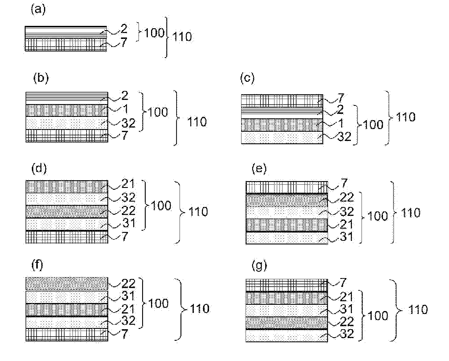
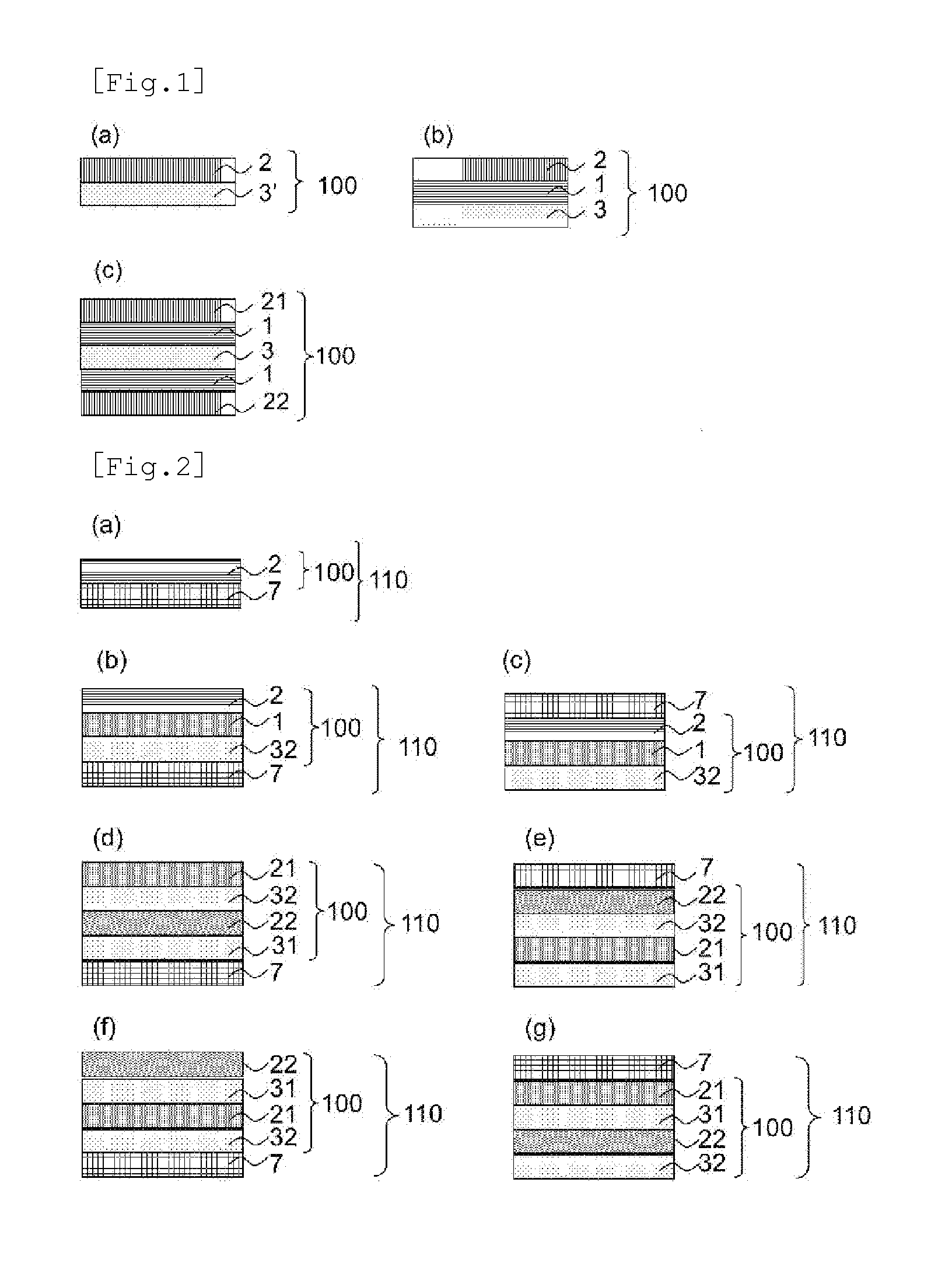
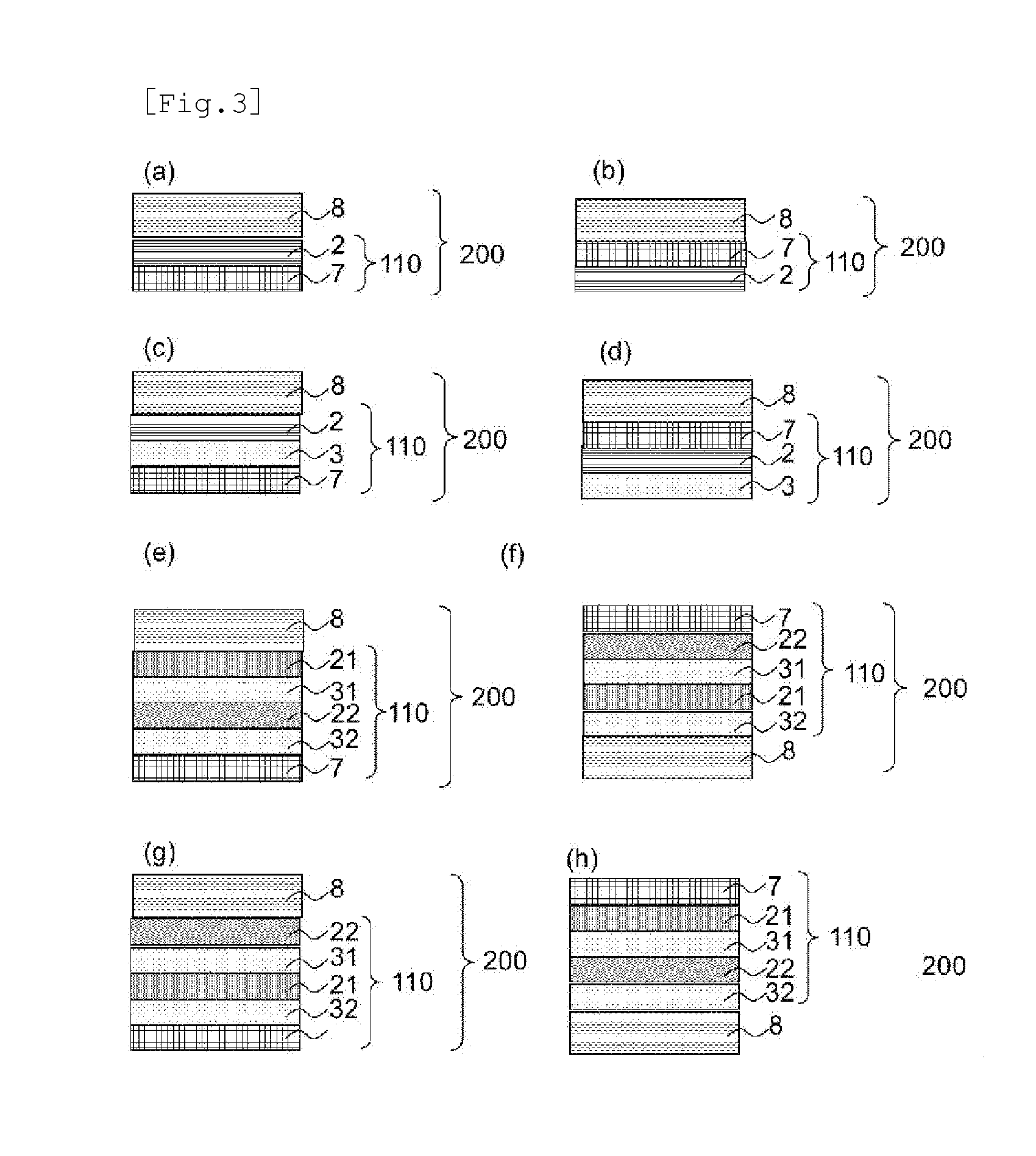
  • Optical film
  • Optical film
  • Optical film

Examples


example 1

Production of Optically Anisotropic Layer

[0211]A cycloolefin polymer film (COP) (ZF-14, manufactured by ZEON CORPORATION) was once treated by a corona treatment apparatus (AGF-B10, manufactured by Kasuga Electric Works Ltd.) in conditions of an output power of 0.3 kW and a treatment speed of 3 m / minute. The composition for forming an orientation layer (1-2) was applied to the corona-treated surface by a bar coater, dried at 80° C. for 1 minute, and then exposed to polarized UV at an integrated light quantity of 100 mJ / cm2 using a polarized UV irradiation device (SPOT CURE SP-7; manufactured by Ushio, Inc.). The thickness of the resulting orientation layer was measured by an Ellipsometer to find the results shown in Table 2. Successively, the polymerizable liquid crystal composition (A-1) was applied onto the orientation layer by a bar coater, dried at 120° C. for 1 minute, followed by irradiation with ultraviolet rays (in nitrogen atmosphere, wavelength: 365 nm, integrated light qua...

example 2

[0213]An optical film 1 including an optically anisotropic layer was obtained in the same manner as in Example 1, except that the composition for forming an orientation layer (1-3) was used as the composition for forming an orientation layer. The thickness of the orientation layer and the observation results of the retardation unevenness in the optical film 1 are shown in Table 2.

example 3

[0214]An optical film 1 including an optically anisotropic layer was obtained in the same manner as in Example 1, except that the composition for forming an orientation layer (1-4) was used as the composition for forming an orientation layer. The thickness of the orientation layer and the observation results of the retardation unevenness in the optical film 1 are shown in Table 2.


PUM


Abstract

A flat panel display device (FPD) makes use of a member including an optical film such as a polarizing plate or a retardation plate. As such an optical film, known is an optical film produced by applying a composition containing a polymerizable liquid crystal compound to a substrate. However, in a conventional optical film, retardation unevenness is generated in a film plane and an optical compensation characteristic for suppressing light leakage attributed to such retardation unevenness during black display of a display device is not sufficient. The present invention, therefore, provides an optical film having an orientation layer containing a leveling agent and an optically anisotropic layer formed on the orientation layer.

Description

BACKGROUND OF THE INVENTION[0001]1. Field of the Invention[0002]The present invention relates to an optical film having an optically anisotropic layer.[0003]2. Description of the Related Art[0004]A flat panel display device (FPD) makes use of a member including an optical film such as a polarizing plate or a retardation plate. As such an optical film, known is an optical film produced by applying a composition containing a polymerizable liquid crystal compound to a substrate. For example, JP-T-2010-537955 describes an optical film exhibiting a reverse-wavelength dispersion property.SUMMARY OF THE INVENTION[0005]However, in a conventional optical film, retardation unevenness is generated in a film plane and an optical compensation characteristic for suppressing light leakage attributed to such retardation unevenness during black display of a display device is not sufficient.[0006]The present invention includes the following.[1] An optical film having a orientation layer containing a ...

Claims


Application Information

Patent Timeline
IPC IPC(8): G02B5/30B05D3/06H01L51/52
CPCG02B5/3016B05D3/065H01L51/5293G02B5/3083H10K59/8791H10K50/86
Inventor KASAI, TATSUAKIKOBAYASHI, TADAHIRO
Owner SUMITOMO CHEM CO LTD
Learn More