Cathodes capable of operating in an electrochemical reaction, and related cells, devices, and methods

a technology of cathodes and electrochemical reactions, applied in the direction of aqueous electrolyte fuel cells, electrochemical generators, indirect fuel cells, etc., can solve the problems of high material cost of currently-used electrode materials, inability to fully scale, and inhibit the widespread penetration of rfb's into the mark

Inactive Publication Date: 2016-05-19
GENERAL ELECTRIC CO
View PDF0 Cites 9 Cited by
  • Summary
  • Abstract
  • Description
  • Claims
  • Application Information

AI Technical Summary

Benefits of technology

This patent describes a new invention that has certain benefits. The technical effects of this invention will be explained in detail in the following description.

Problems solved by technology

However, EES technologies that are currently available often operate at high cost, and / or are not truly scalable.
However, the low energy density (20-50 Wh / kg) and high material cost of currently-used electrode materials (e.g., vanadium or bromine) inhibit the widespread penetration of RFB's into the market.
With the exception of an expensive all-vanadium device, most other RFB chemistries include catholyte-anolyte systems that may be susceptible to cross-contamination.
The contamination cannot be prevented by the use of ion exchange membranes, and thus become a major problem that can require reprocessing of active materials.
Additional processing steps like this can increase maintenance cost and downtime, and decrease the life of the RFB's devices.
While highly advanced battery chemistries like lithium ion have shown great promise for use in modern EV's, serious drawbacks remain.
For example, the battery systems still usually represent the most expensive, and heaviest component in the EV.
This can, in turn, place greater demands on the battery; and can lower the operational time before recharging is necessary.
Unlike lithium ion and other types of battery systems, flow batteries can conveniently separate cathode and anode components in a physical sense, and this may decrease the danger that can arise when a battery's electrode components are located next to each other.

Method used


Image

  • Cathodes capable of operating in an electrochemical reaction, and related cells, devices, and methods
  • Cathodes capable of operating in an electrochemical reaction, and related cells, devices, and methods
  • Cathodes capable of operating in an electrochemical reaction, and related cells, devices, and methods

Examples


Embodiment Construction

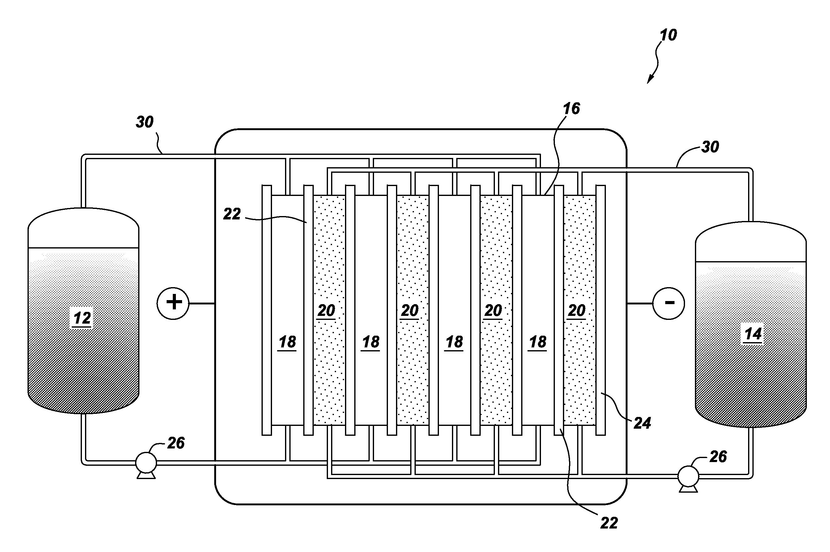
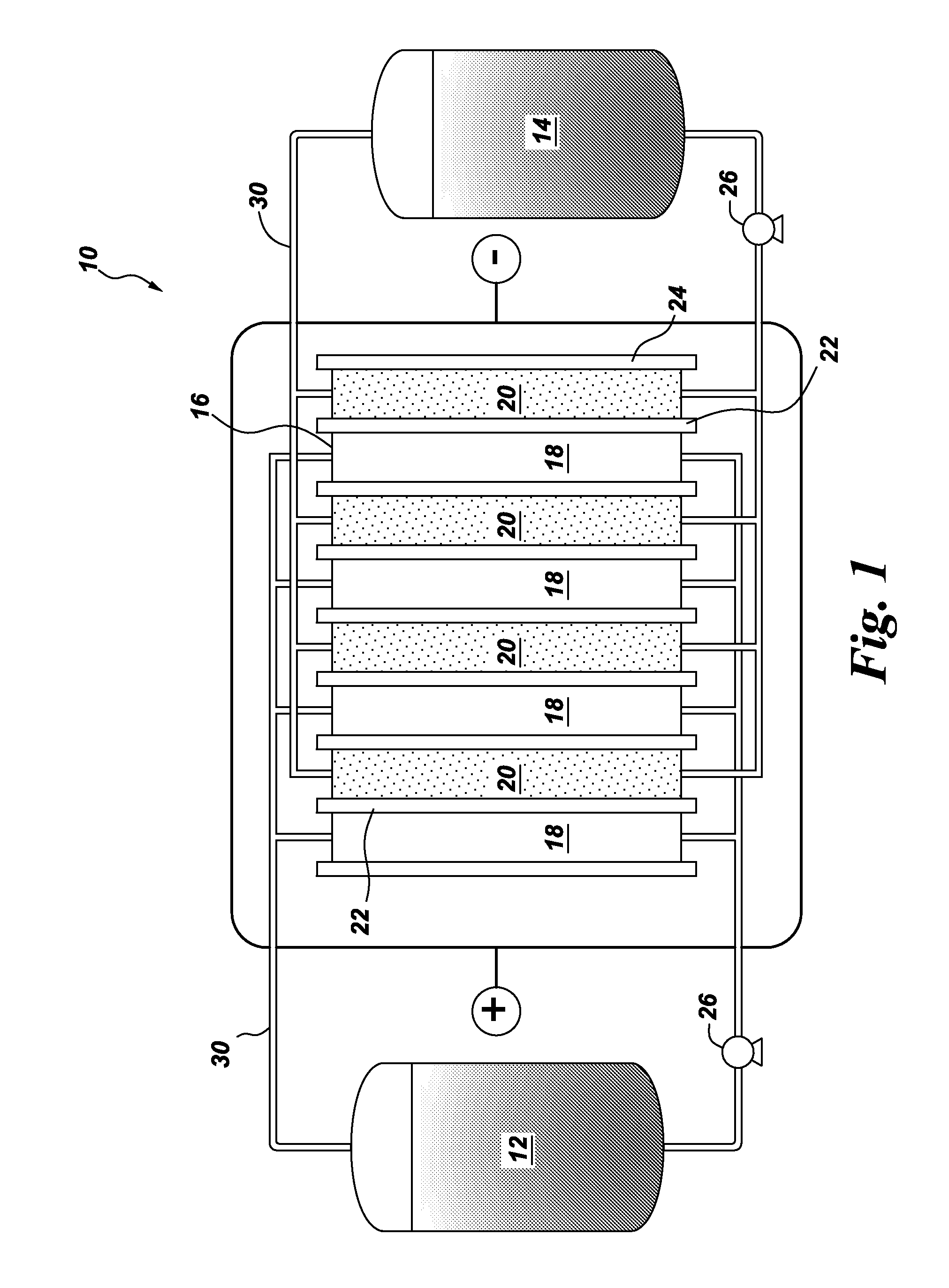
[0012]One embodiment of the invention is directed to a flow battery that contains at least one electrochemical cell. One or more of the electrochemical cells comprise a halogen oxoacid salt, and an anode. The anode may comprise a liquid organic hydrogen carrier, or a metal. Usually, the oxoacid compound conforms to the general formula HXO3, where X is chlorine, bromine, or iodine. The corresponding salts are the chlorate salt, the bromate salt, and the iodate salt, respectively.

[0013]In the case of chlorine, the corresponding salt of chloric acid (i.e, the chlorate) is often selected from the group consisting of sodium chlorate, potassium chlorate, lithium chlorate, calcium chlorate, magnesium chlorate, zinc chlorate; and combinations thereof. In the case of bromine, the corresponding salt of bromic acid (i.e., the bromate) is often selected from the group consisting of sodium bromate, potassium bromate, lithium bromate, calcium bromate, magnesium bromate, zinc chlorate; and combina...


PUM


Abstract

A flow battery is described, including a catholyte in the form of an aqueous solution of at least one salt of a halogen oxoacid compound; and an anolyte that includes an eletrochemically-active material capable of participating in a reduction-oxidation (redox) reaction with the catholyte salt; along with an intervening ion-permeable membrane. A unique cathode used in the battery or for other purposes is also described, along with a method of providing electrical energy to a device, system, or vehicle, using the flow battery.

Description

CROSS REFERENCE TO RELATED PATENT APPLICATIONS[0001]This application is a national stage application under 35 U.S.C. §371(c) of prior filed, co-pending PCT application serial number PCT / US2014 / 041374, filed on Jun. 6, 2014, which claims priority to U.S. Provisional Applications Ser. No. 61 / 832,236 (G. Soloveichik et al), filed on Jun. 7, 2013; and Ser. No. 61 / 832,221 (G. Soloveichik), filed on Jun. 7, 2013. The contents of both of these Applications are incorporated herein by reference.BACKGROUND[0002]Grid-scale electrical energy storage (EES) refers to methods that store electricity on a large scale, within an electrical power grid. In brief, electrical energy is stored during times when production from power plants exceeds consumption. The stored power is used at times when consumption exceeds production. In this manner, the production of electric power can be maintained at a more constant level. Thus, fuel-based power plants (i.e. coal, oil, gas) can be more efficiently and easil...

Claims


Application Information

Patent Timeline
IPC IPC(8): H01M8/08H01M8/20H01M8/18
CPCH01M8/08H01M8/188H01M2300/0005H01M2250/20H01M2250/10H01M8/20Y02E60/50Y02B90/10Y02T90/40
Inventor SOLOVEICHIK, GRIGORII LEVKNIAJANSKI, SERGEIZAPPI, GUILLERMO DANIEL
Owner GENERAL ELECTRIC CO
Why Eureka
Try Eureka