
Image processing device, imaging device, image processing method, and program

a technology of image processing and imaging device, applied in the field of image processing device, imaging device, image processing method, program, etc., can solve the problems of image quality deterioration and image quality deterioration, and achieve the effect of suppressing deterioration of image quality, suppressing a rapid change of content, and preventing deterioration

Active Publication Date: 2016-05-19
FUJIFILM CORP
View PDF6 Cites 9 Cited by
  • Summary
  • Abstract
  • Description
  • Claims
  • Application Information

AI Technical Summary

Benefits of technology

The invention is about a method for improving the quality of moving images. It involves using information from a reference frame to control the restoration process for the main frame. This helps to keep the restoration process continuous and smooth, even if there are sudden changes in the environment. As a result, the method helps to maintain image quality and prevents rapid deterioration over time.

Problems solved by technology

While improvement of image quality is basically expected if the restoration process is performed, the restoration process may cause deterioration of image quality.
In addition, if a restoration process is performed for a saturated pixel or a defocus region, image quality may be deteriorated, and various methods which cope with image quality deterioration due to the restoration process for the saturated pixel or the defocus region have been suggested.

Method used


Image

  • Image processing device, imaging device, image processing method, and program
  • Image processing device, imaging device, image processing method, and program
  • Image processing device, imaging device, image processing method, and program

Examples


first embodiment

[0111]FIG. 5 is a functional block diagram relating to a restoration process for a moving image of a first embodiment, and shows various functional blocks constituted by the image processing unit 35 (see FIG. 2). The functional blocks in the drawing may not necessarily be provided separately, and a plurality of functional blocks may be realized by integrally configured hardware / software.

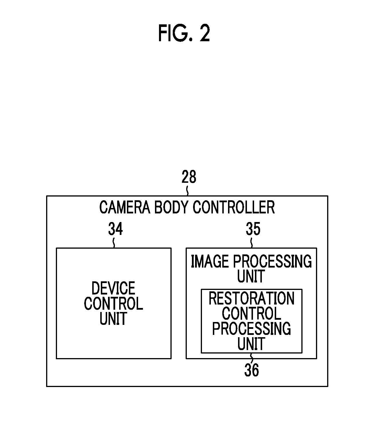
[0112]The image processing unit 35 includes a buffer memory unit 41 and a restoration control processing unit 36, and the restoration control processing unit 36 includes a restoration adjustment unit 43 and a restoration execution unit 45. The buffer memory unit 41 and the restoration control processing unit 36 (the restoration adjustment unit 43 and the restoration execution unit 45) can perform communication of data with each other.

[0113]The buffer memory unit 41 temporarily stores image data of a plurality of continuous frames in a time series acquired by photographing using the optical system 12 ...

second embodiment

[0160]In this embodiment, the process content of the restoration process is changed based on motion of the object, thereby performing a more appropriate restoration process even for a moving image where an object moves.

[0161]In this embodiment, description of the same configuration and action as in the first embodiment described above will not be repeated.

[0162]FIG. 14 is a functional block diagram relating to a restoration process of a second embodiment, and shows various functional blocks constituted by the image processing unit 35 (see FIG. 2).

[0163]The image processing unit 35 includes a buffer memory unit 41, a restoration control processing unit 36, and an object detection unit 47, and the buffer memory unit 41, the restoration control processing unit 36, and the object detection unit 47 can perform communication of data with one another.

[0164]The object detection unit 47 detects motion of an object (main object) in a moving image having a plurality of continuous frames in a t...

third embodiment

[0168]In this embodiment, the restoration adjustment unit 43 performs the adjustment of the restoration process based on the image information of the frame to be processed and the reference frame.

[0169]In this embodiment, description of the same configuration and action as in the first embodiment described above will not be repeated. A region Q which is unsuitable for the restoration process refers to a region having characteristics such that image quality is deteriorated if the restoration process is performed. For example, the region Q which is unsuitable for the restoration process is a defocus (not focused on the object) region. That is, since image quality is deteriorated if the restoration process is performed for the defocus region, the defocus region is the region Q which is unsuitable for the restoration process.

[0170]For example, as the region Q which is unsuitable for the restoration process, a region where a saturated pixel is detected is considered. That is, if the rest...


PUM


Abstract

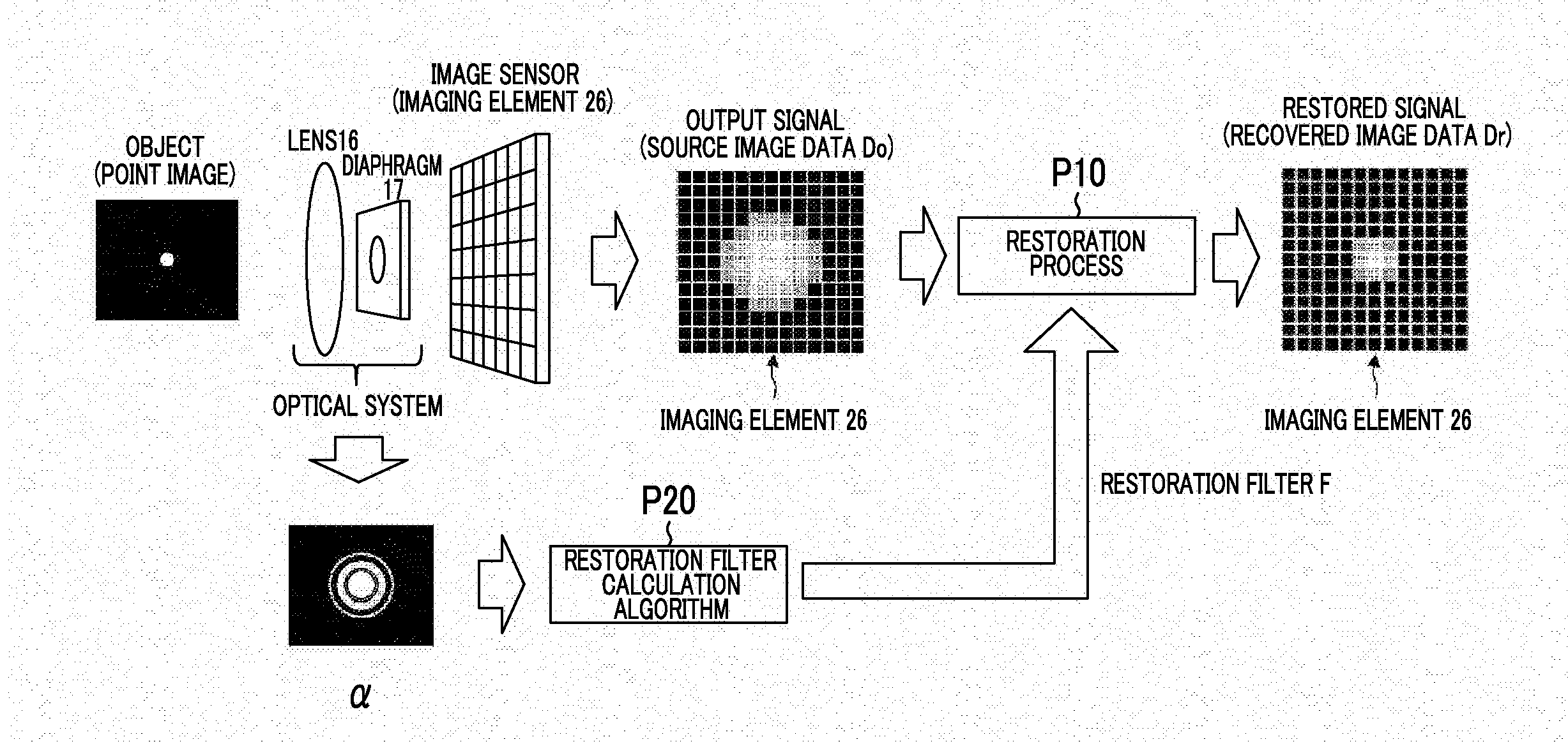
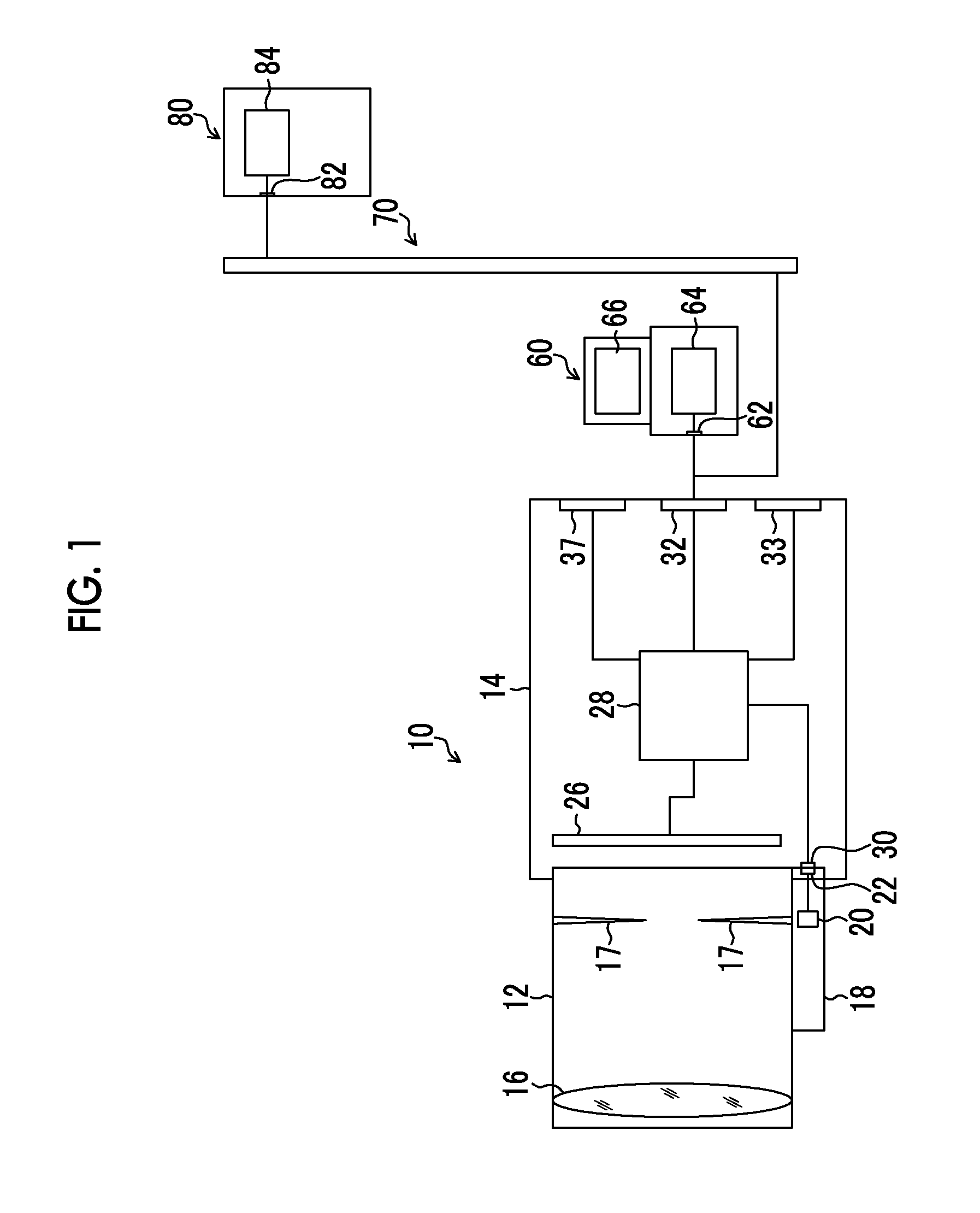
Disclosed are an image processing device, an imaging device, an image processing method, and a program capable of acquiring a moving image with excellent image quality while maintaining continuity of a restoration process between frames even if there is a rapid change of a photographing environment in a moving image. An image processing device includes a restoration control processing unit 36 which subjects a moving image including a plurality of frames acquired by photographing using an optical system to a restoration process based on a point spread function of the optical system to acquire recovered image data. The restoration control processing unit 36 controls the restoration process for a frame to be processed among a plurality of frames based on imaging information of a reference frame including a frame after the frame to be processed in a time series.

Description

CROSS-REFERENCE TO RELATED APPLICATIONS[0001]This application is a Continuation of PCT International Application No. PCT / JP2014 / 066431 filed on Jun. 20, 2014, which claims priority under 35 U.S.C. §119(a) to Patent Application No. 2013-161616 filed in Japan on Aug. 2, 2013, all of which are hereby expressly incorporated by reference into the present application.BACKGROUND OF THE INVENTION[0002]1. Field of the Invention[0003]The present invention relates to an image processing device, an imaging device, an image processing method, and a program, and in particular, to an image processing device, an imaging device, an image processing method, and a program which perform a restoration process based on a point spread function.[0004]2. Description of the Related Art[0005]In an object image photographed through an imaging optical system, a so-called point spread phenomenon in which a point object has minute spread due to the influence of diffraction, aberration, or the like caused by the i...

Claims


Application Information

Patent Timeline
Patent Type & Authority Applications(United States)
IPC IPC(8): G06T5/00G06T7/20H04N5/225G06T5/20H04N23/75
CPCG06T5/003G06T5/20G06T2207/20201H04N5/225G06T2207/10016G06T7/20G06T2207/20192G06T5/50H04N23/80G06T5/73H04N23/958H04N23/00
Inventor SUGIMOTO, MASAHIKOHAYASHI, KENKICHINARUSE, YOUSUKEIRIE, KOSUKE
Owner FUJIFILM CORP
Learn More