
Semiconductor light-emitting apparatus and vehicle headlight

a semiconductor light-emitting device and semiconductor technology, applied in semiconductor lasers, fixed installations, lighting and heating apparatus, etc., can solve the problems of emitting strong light having a considerable non-uniform white color tone toward the road, and the semiconductor light-emitting device b>100/b> may continuously not provide drivers with clear road conditions to drive safely, etc., to achieve a favorable light distribution pattern and simple structure

Active Publication Date: 2016-05-12
STANLEY ELECTRIC CO LTD
View PDF0 Cites 14 Cited by
  • Summary
  • Abstract
  • Description
  • Claims
  • Application Information

AI Technical Summary

Benefits of technology

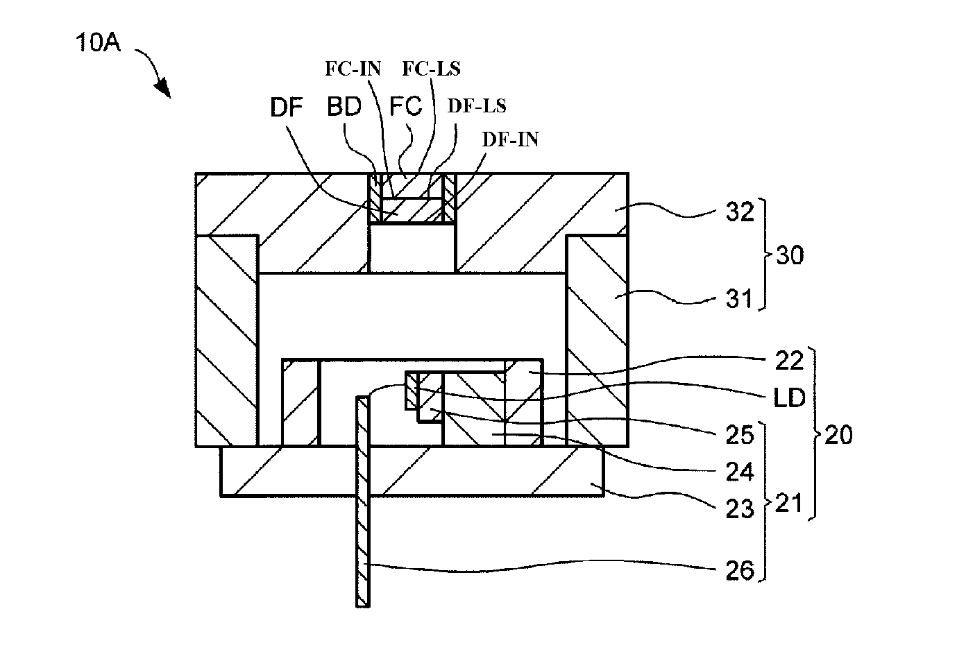
The invention provides reliable semiconductor light-emitting apparatuses that can emit various color lights including a substantially white color light with favorable optical characteristics. The apparatuses can be used for vehicle lamps and the like, and can also include an optical fiber. The invention also provides vehicle headlights using the reliable semiconductor light-emitting apparatuses, which can provide a favorable light distribution pattern even after long periods of usage in a small sealed housing.

Problems solved by technology

However, the headlight, in which the semiconductor light-emitting device 100 having such a structure is combined with the optical devices such as the reflector, the projector lens and the like, may emit the strong light having a considerable non-uniform white color tone toward the road because the light having a slightly color variation is enlarged by the optical devices and may be projected toward the road.
Therefore, the headlight using the conventional semiconductor light-emitting device 100 may continuously not provide drivers with clear road conditions to drive safely at night.

Method used


Image

  • Semiconductor light-emitting apparatus and vehicle headlight
  • Semiconductor light-emitting apparatus and vehicle headlight
  • Semiconductor light-emitting apparatus and vehicle headlight

Examples


Embodiment Construction

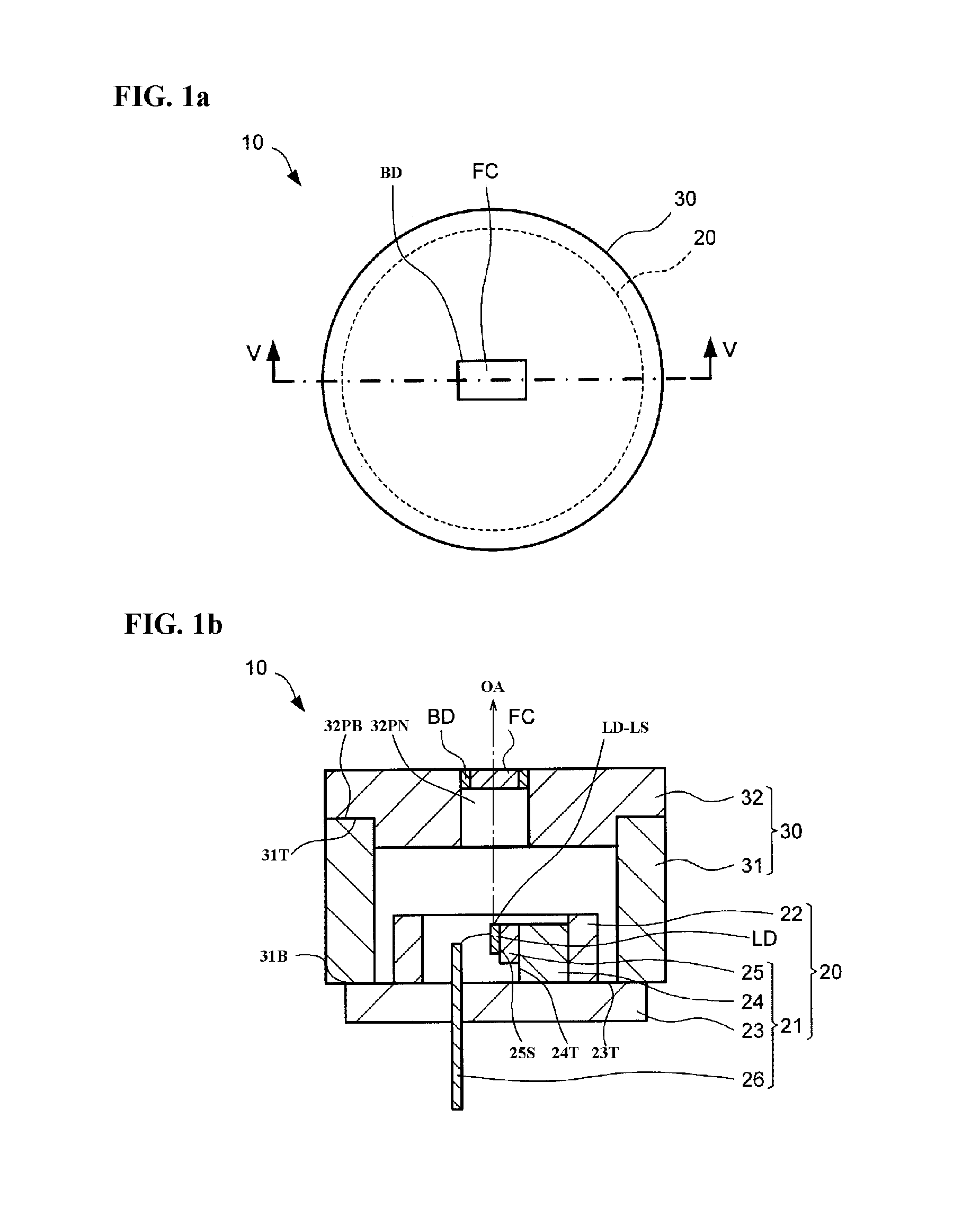
[0036]Exemplary embodiments of the disclosed subject matter will now be described in detail with reference to FIG. 1a to FIG. 6b, in which the same or corresponding elements use the same reference marks. FIG. 1a is a schematic enlarged top view showing a first exemplary embodiment of a semiconductor light-emitting apparatus made in accordance with principles of the disclosed subject matter, andFIG. 1b is a schematic enlarged cross-sectional view showing the first embodiment of the semiconductor light-emitting apparatus taken along Line V-V shown in FIG. 1a.

[0037]The semiconductor light-emitting apparatus 10 can include a laser chip LD having electrodes, a laser optical axis OA and a laser light-emitting surface LD-LS, and a package 20 including a stem 21 to mount the laser chip LD and a sealing portion 22 to cover the laser chip LD, the stem 21 including a base board 23 having a base top surface 23T, a heat sink 24 having a sink top surface 24T located on the base top surface 23T o...


PUM


Abstract

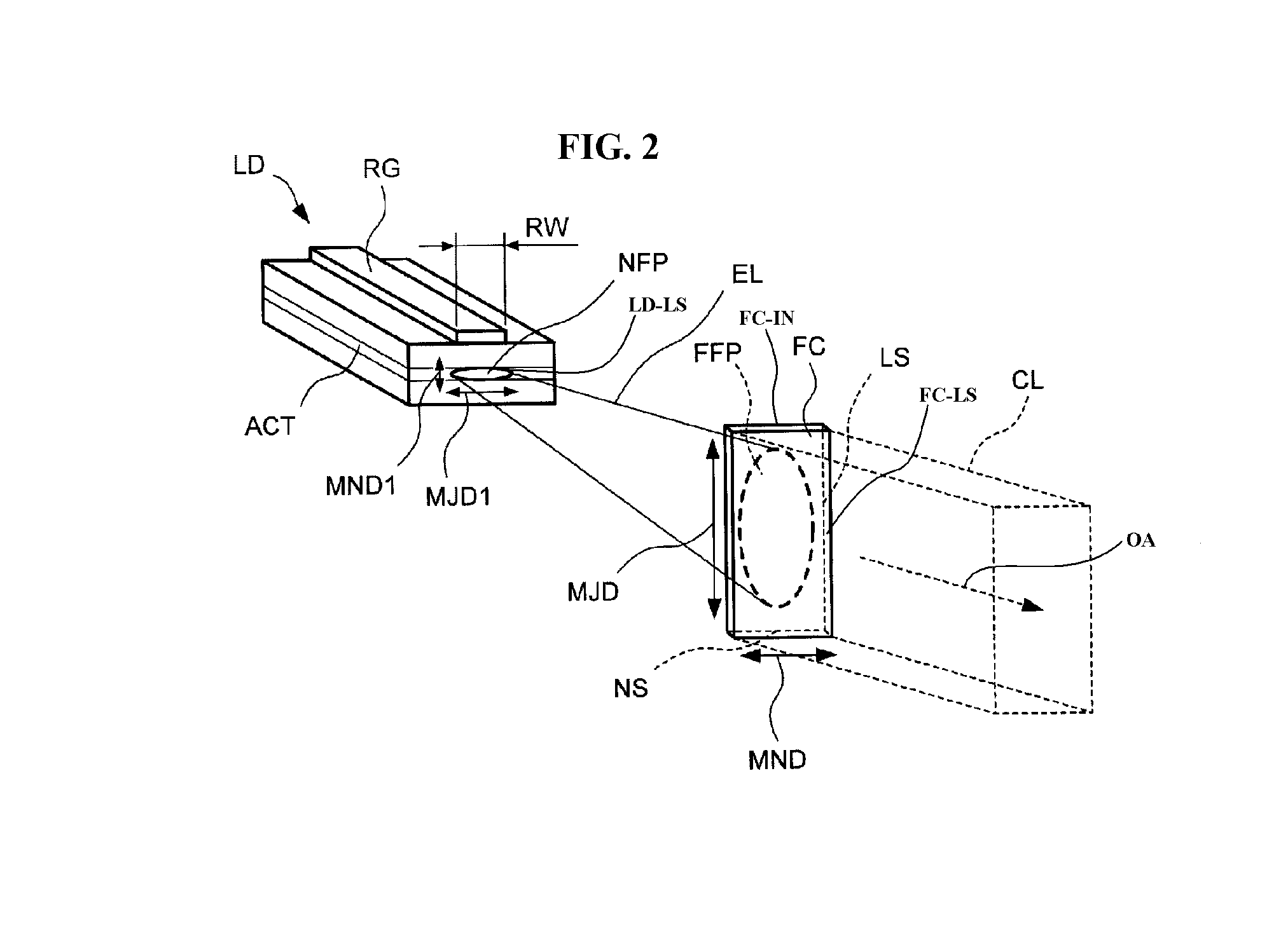
A reliable semiconductor light-emitting apparatus and a headlight using the light-emitting apparatus provided with a laser chip having a diffraction performance and a wavelength converting board. The wavelength converting board can uniformly receive a laser beam emitted from the laser chip, which includes a laser beam having a relatively high intensity near an optical axis of the laser chip, from an incident surface thereof by locating the wavelength converting board with a prescribed locating relation with respect to the laser chip, and can emit a mixture light having a substantially uniform color tone including white light and a high light-emitting intensity from a light-emitting surface thereof. Thus, the disclosed subject matter can provide reliable semiconductor light-emitting apparatuses that can emit various color lights having favorable optical characteristics, which can also include the optical fiber, and which can be used for the headlight that can provide a favorable light distribution pattern.

Description

[0001]This application claims the priority benefit under 35 U.S.C. §119 of Japanese Patent Application No. 2014-229111 filed on Nov. 11, 2014, which is hereby incorporated in its entirety by reference.BACKGROUND[0002]1. Field[0003]The presently disclosed subject matter relates to semiconductor light-emitting apparatuses in which light emitted from a semiconductor laser device is wavelength-converted by a wavelength converting board, and to vehicle headlights using the semiconductor light-emitting apparatuses. More particularly, the disclosed subject matter relates to reliable semiconductor light-emitting apparatuses having favorable optical characteristics, which can be used for a vehicle headlight with a simple structure, and to the vehicle headlights using such light-emitting apparatuses.[0004]2. Description of the Related Art[0005]Semiconductor light-emitting devices, in which a part of light emitted from a semiconductor light-emitting chip is converted into light having a differ...

Claims


Application Information

Patent Timeline
IPC IPC(8): F21K99/00F21S8/10H01S5/22H01S5/323H01S5/022
CPCF21K9/56H01S5/32341H01S5/02252F21Y2101/025F21S48/1186F21S48/125F21S48/1317H01S5/22H01S5/02212F21Y2101/00F21Y2115/30F21S41/25F21S41/16H01L2224/48091F21K9/64F21S41/176H01S5/02257H01S5/02251H01S5/0087H01L2924/00014H01S5/02326H01S5/02253H01S5/02255
Inventor WARAGAYA, TAKESHI
Owner STANLEY ELECTRIC CO LTD
Learn More